Responses
- AI Agent
- Data Types\Number\Operations
- Data Types\Number\ Variable
- Data Types\Number\ Compare
- Data Types\Number\ Conversion
- Data Types\Number\ Expression
- Data Types\Boolean\ Expression
- Data Types\Time
- Scene State
- Sequence
- User
- User \ Controller
- User \ Transform
- User \ Gadget
- User \ Attributes
- User \ Point To Object
- User \ Set Mode
- User Name & ID
- Material
- Material \ Texture
- Execution
- SceneNode \ Management
- SceneNode \ Transform
- SceneNode \ Transform \ Location
- SceneNode \ Grab
- Resource
- External Connection \ WebSocket
- Media
- Media \ Variable Writer \
- Media \ Dynamic Menu
- Media \ Sound
- Media \ Video
- Cloud
- Scene
- Integration
- SceneNode \ Snapping
- SceneNode \ Hierarchy
- SceneNode \ Appearance
- SceneNode \ Curve
- Device / Attributes
- SceneNode \ Transform \ Scale
- SceneNode \ Transform \ Rotation
- User \ Observe
- SceneNode \ Attributes
- SceneNode \ Assembly
- Variable
- Cloud \ Dynamic Attributes
AI Agent
 AI Agent Reset Chat History

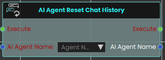 The AI Agent Reset Chat History node enables the system to clear and reset the ongoing conversation history for a specific AI Agent. It is typically used when you want the AI to start a completely fresh interaction or switch to a new scenario without being influenced by the context of any prior messages.
 AI Agent Send Message
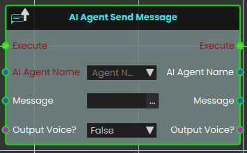
The AI Agent Send Message node enables the system to send a specific text message to an assigned AI Agent for processing. The Output Voice? boolean parameter that dictates how the AI agent will deliver its response:
-
False: The AI agent will respond with text.
-
True: The AI agent will process the text message and respond with generated voice audio.
AI Agent Send Voice Message
Has one of your scene’s AI agents deliver a pre-recorded voice file to a user.
What it does
This node tells the AI agent you name to play a voice file for a user. You choose which agent speaks, who hears it, and which sound file to use. It’s a handy way to have an agent greet someone, give an instruction, or read out a scripted message without typing live text.
The node only sends the message — it doesn’t change the agent, the user, or the voice file in any way. Every value you feed in is also handed straight back out, so you can pass the same agent, user, or file along to the next node in your sequence.
Inputs
| Port | Type | What to connect |
|---|---|---|
| Execute | Trigger | Wire this from the previous node’s Execute output. |
| AI Agent Name | Text | The name of the AI agent that should speak. Pick one of the agents set up in your scene. |
| User | User | The person who should hear the message. Leave it on Host Only to send it just to the host, or connect a user to target someone specific. |
| Voice File | Text | The name of the voice file the agent should play. |
| Output Voice? | True / false | Set to true to have the message played aloud as voice, or false to send it without sound. Defaults to true. |
Outputs
| Port | Type | What you get |
|---|---|---|
| Execute | Trigger | Fires once the node has finished. |
| AI Agent Name | Text | The same agent name you connected, passed along so you can reuse it. |
| User | User | The same user you connected, passed along unchanged. |
| Voice File | Text | The same voice file name you connected, passed along unchanged. |
| Output Voice? | True / false | The same true/false setting you connected, passed along unchanged. |
Example
| AI Agent Name input | Guide |
| User input | Host Only |
| Voice File input | welcome_message.wav |
| Output Voice? input | true |
| Voice File output | welcome_message.wav |
 AI Agent Start Listen

The AI Agent Start Listen node is used to make the AI start listening to the user. When activated, this node enables the AI to process and listen to spoken input from the user, allowing for interactive conversations and commands within the VR environment.
Example

In this example, an AI Doctor is set up in the AI Agents window. This window can be accessed by clicking the Interaction icon in the viewport menu, then select the AI Agents, and then add the AI name with the desired instructions in the Instructions field. A variable is created to store the AI's responses.

The AI Agent Start Listen node is used to make the AI Agent named Doctor start listening to the user when the object named "Start" is triggered. This setup enables the AI to process and listen to user input as soon as the trigger event is activated.
 AI Agent Stop Listen

The AI Agent Stop Listen node is used to make the AI stop listening to the user. When activated, this node halts the AI’s ability to process further user input, allowing the AI to respond based on the information gathered up to that point.
Example
In this example, an AI Doctor is set up in AI Agents window. This window can be accessed by clicking the Interaction icon in the viewport menu, then select the AI Agents, and then add the AI name with the desired instructions in the Instructions field. A variable is created to store the AI's responses.

The AI Agent Stop Listen node is used to stop the AI Agent from listening to the user when the "Stop" trigger event occurs. This allows the AI agent named Doctor to respond based on the input received before listening was stopped.
AI Agent Stop Listen (Text)
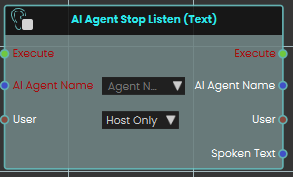
The AI Agent Stop Listen (Text) node is used to make the AI stop listening to the user. When activated, this node halts the AI’s ability to process further user input, allowing the AI to respond based on the information gathered up to that point.
This node has an extra output "Spoken Text", when the node is activated, it outputs the input audio in text format.
 Has Valid AI Key

The Has Valid AI Key node checks whether a valid AI key is available for AI-related features in Sim Lab Composer. This node ensures that AI functionalities can operate properly by verifying the presence of an active and valid AI key.
Example
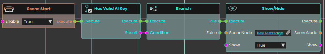
In this example, the Has Valid AI Key node is used at the start of the scene to check if the user has an activated AI key. The node is connected to a Branch node, where the False output (indicating no valid AI key) triggers a message in front of the user, informing them that the AI key must be activated.
 Set AI Key

The Set AI Key node allows you to assign an AI API key to a VR experience directly from the Training Builder. This lets the experience use AI features without requiring the user to manually activate an API key in the viewer. You can select the provider (OpenAI, Gemini, or OpenRouter) and embed the corresponding API key into the experience.
Example
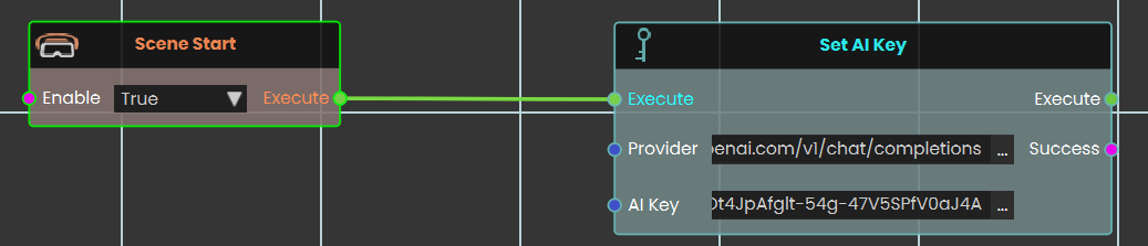
In this example, the Set AI Key node is connected to a Scene Start event to initialize the AI provider as soon as the experience begins. After adding the node and selecting the provider, the API key is pasted into the node’s field. The key is then activated when the scene starts, allowing the AI agent to respond without the user needing their own key. If the embedded key is not active or reaches its usage limit, the experience automatically switches to the user’s API key in the viewer if one is available.
Check this tutorial for more about this node.
 Set AI Agent Model

The Set AI Agent Model node is used to assign a specific AI provider and model to an AI agent in your VR experience. This ensures the AI agent will operate using the selected provider and model for any interactions that occur in the scene. You can choose the AI agent you have created, specify the provider (OpenAI, Gemini, or OpenRouter), and define the model name.
Example
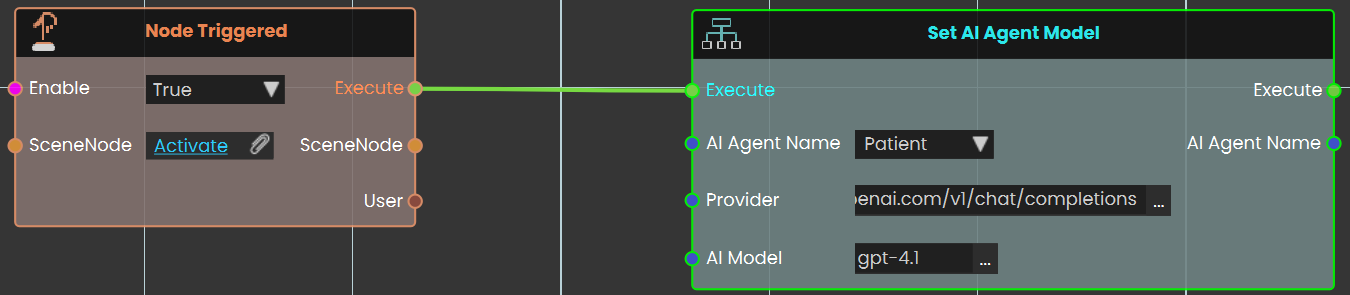
In this example, the Set AI Agent Model node is triggered by pressing a button in the VR scene. When the button is clicked, the node assigns the “Patient” AI agent to the OpenAI provider and sets the model to GPT‑4. This setup allows the AI agent to function with the defined provider and model as soon as the event is triggered.
Check this tutorial for more about this node.
Using AI Providers and API Keys in SimLab Composer
SimLab Composer now supports OpenAI, Google Gemini, and OpenRouter for integrating AI into your VR experiences. With the new Set AI Key and Set AI Agent Model nodes, you can connect your experience to these providers .
Providers and Models:
1️⃣ OpenAI
-
Provider URL:
https://api.openai.com/v1/chat/completions -
Models:
-
gpt-4.1
-
gpt-4
-
gpt-3.5-turbo
-
2️⃣ Google Gemini (OpenAI‑compatible endpoint)
-
Provider URL:
https://generativelanguage.googleapis.com/v1beta/openai/chat/completions -
Models:
-
gemini‑2.0‑flash
-
3️⃣ OpenRouter
-
Provider URL:
https://openrouter.ai/api/v1/chat/completions -
Models:
-
openrouter/cypher‑alpha:free
-
nvidia/llama‑3.3‑nemotron‑super‑49b‑v1:free
-
OpenAI keys work with Chat, Text‑to‑Speech, and Speech‑to‑Text.
-
Gemini and OpenRouter keys work with Text only.
-
-
Data Types\Number\Operations
 Add
Add

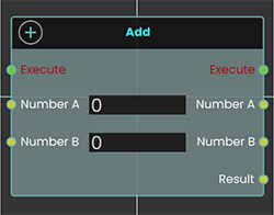
The Add response enables user to add two values by either typing in a numerical value in Number A and Number B field or by attaching a value or a variable node to those ports, then once the response is executed the resulting value can be acquired through the Result port.
Example
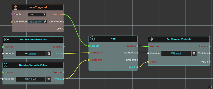
In this Example an Add Response is used to add the values of 5 to the value of Variable1 once the user triggers the object named Activate, and the result of the addition is then written in a variable named Result, which can then be connected to a variable writer to be displayed during the VR Experience.
 Ceiling
The Ceiling response enables the user to round up a value by either typing in a numerical value in the Number A field or by attaching a value or a variable node to that port. Then once the response is executed, the smallest integral value greater than or equal to the input value can be acquired through the Result port.
Example
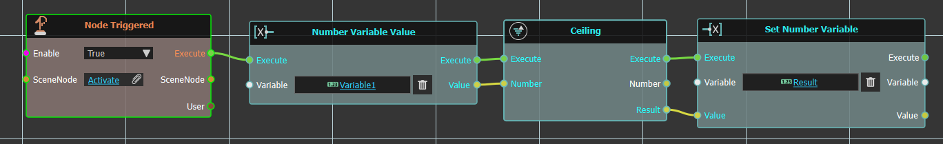
In this example, a Ceiling Response is used to round up the value of Variable1 to the smallest integral value greater than or equal to it once the user triggers the object named Activate. The result of the ceiling operation is then written in a variable named Result, which can then be connected to a variable writer to be displayed during the VR Experience.
 Divide
The Divide response enables user to divide a value by another value, by either typing in a numerical value in Number A and Number B field or by attaching a value or a variable node to those ports, then once the response is executed the resulting value can be acquired through the Result port.
Example
In this Example a Divide Response is used to divide the number 25 by the value of the variable named "Variable1" and the result of the division is then written in a variable named Result, which can then be connected to a variable writer to be displayed during the VR Experience.
 Floor
Floor
The Floor response enables the user to round down a value by either typing in a numerical value in the Number A field or by attaching a value or a variable node to that port. Then once the response is executed, the largest integral value less than or equal to the input value can be acquired through the Result port.
Example
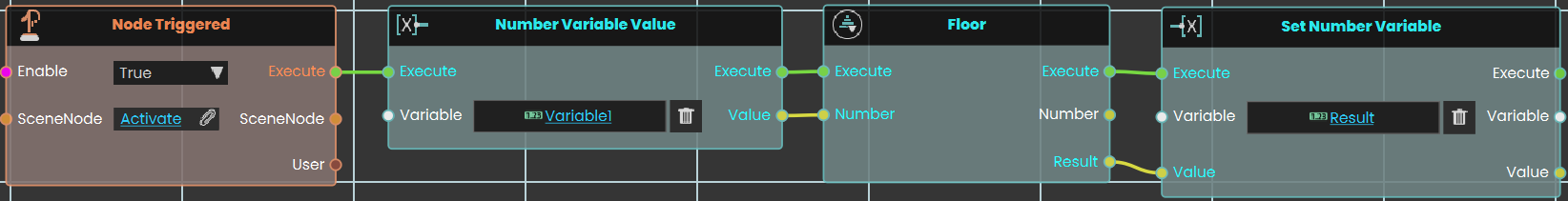
In this example, a Floor Response is used to round down the value of Variable1 to the largest integral value less than or equal to it once the user triggers the object named Activate. The result of the floor operation is then written in a variable named Result, which can then be connected to a variable writer to be displayed during the VR Experience.
![]() Modulo
Modulo
The Modulo response enables the user to find the remainder of a division by either typing in numerical values in the Number A and Number B fields or by attaching values or variable nodes to those ports. Then once the response is executed, the modulus of the input value with respect to the divisor can be acquired through the Result port.
Example
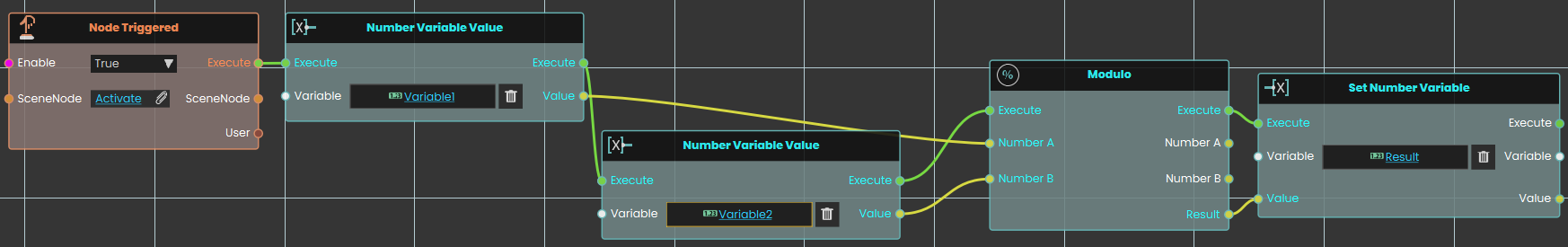
In this example, a Modulo Response is used to calculate the remainder when the value of the variable named Variable1 is divided by the value of Variable2, once the user triggers the object named Activate. The result of the modulo operation is then written in a variable named Result, which can then be connected to a variable writer to be displayed during the VR Experience.
 Multiply
The Multiply response enables user to multiply two values by either typing in a numerical value in Number A and Number B field or by attaching a value or a variable node to those ports, then once the response is executed the resulting value can be acquired through the Result port.
Example
In this Example a Subtract Response is used to subtract the value of Variable1 from the value of the Variable2, then a Multiply Response is used to multiply the subtraction result by 3 once the user triggers the object named Activate, and the result of the multiplication is then written in a variable named Result, which can then be connected to a variable writer to be displayed during the VR Experience.
 Square Root
The Square Root response enables the user to calculate the square root of a value by either typing in a numerical value in the Number field or by attaching a value or a variable node to that port. Then once the response is executed, the square root of the input value can be acquired through the Result port.
Example
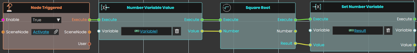
In this example, a Square Root response is used to calculate the square root of the value of Variable1 once the user triggers the object named Activate. The result of the square root operation is then written in a variable named Result, which can then be connected to a variable writer to be displayed during the VR Experience.
 Subtract
The Subtract response enables user to subtract a value from another by either typing in a numerical value in Number A and Number B field or by attaching a value or a variable node to those ports, then once the response is executed the resulting value can be acquired through the Result port.
Example
In this Example a Subtract Response is used to subtract the value of Variable1 from the value of the variable named Variable2, once the user triggers the object named Activate, and the result of the subtraction is then written in a variable named Result, which can then be connected to a variable writer to be displayed during the VR Experience.
Data Types\Number\ Variable
 Set
Set
Has two options:
Set Number Variable By Expression
The Set number variable response enables user to set a value by either typing in a numerical value in the value field or by attaching a value or a variable node to that port. Then once the response is executed, the variable value can be acquired through the Value port.
Example
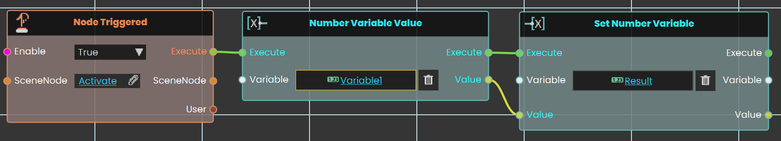
In this example, a Set number variable is used to assign the value of Variable1 once the user triggers the object named Activate, and the new value is then written in a variable named Result, which can then be connected to a variable writer to be displayed during the VR Experience.
Set Number Variable By Expression
The Set number variable by expression response enables user to set a value by either typing in an expression in the expression field or by attaching a value or a variable node to that port. Then once the response is executed, the variable value can be acquired through the Value port.
Example
In this example, a Set Number Variable By Expression is used to set the result of the sum of Variable1 and Variable2 once the user triggers the object named Activate. The new value is then written in the Result variable, which can be connected to a variable writer to be displayed during the VR Experience.
 Decrement Number Variable
The Decrement Number Variable response enables the user to decrease a variable's value by 1 each time the event connected to it is triggered. Once the response is executed, the updated value can be acquired through the Value port.
Example
In this example, a Decrement Number Variable response is used to decrease the value of Variable1 by 1 once the user triggers the object named Activate. The result of the decrease number variable operation is then written in a variable named Result, which can then be connected to a variable writer to be displayed during the VR Experience.
![]() Increment Number Variable
Increment Number Variable
The Increment Number Variable response enables the user to increase a variable's value by 1 each time the event connected to it is triggered. Once the response is executed, the updated value can be acquired through the Value port.
Example
In this example, a Increment Number Variable response is used to increase the value of Variable1 by 1 once the user triggers the object named Activate. The result of the decrease number variable operation is then written in a variable named Result, which can then be connected to a variable writer to be displayed during the VR Experience.
![]() Get
Get
The Number Variable Value response enables the user to get a variable's value each time the event connected to it is triggered. Once the response is executed, the updated value can be acquired through the Value port.
Example
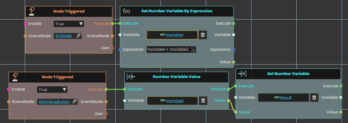
In this example, a Number Variable Value response is used to get the new value for Variable1 after it was changed by Set Number Variable By Expression once the user triggers the object named GetValueButton. The value of the number variable is then written in a variable named Result, which can then be connected to a variable writer to be displayed during the VR Experience.
Data Types\Number\ Compare
 Equal (Number)
The Equal (Number) response enables the user to compare two values by either typing in a numerical value in the Number A and Number B fields or by attaching a value or a variable node to those ports. Then once the response is executed, the result of the comparison can be acquired through the Result port.
Example
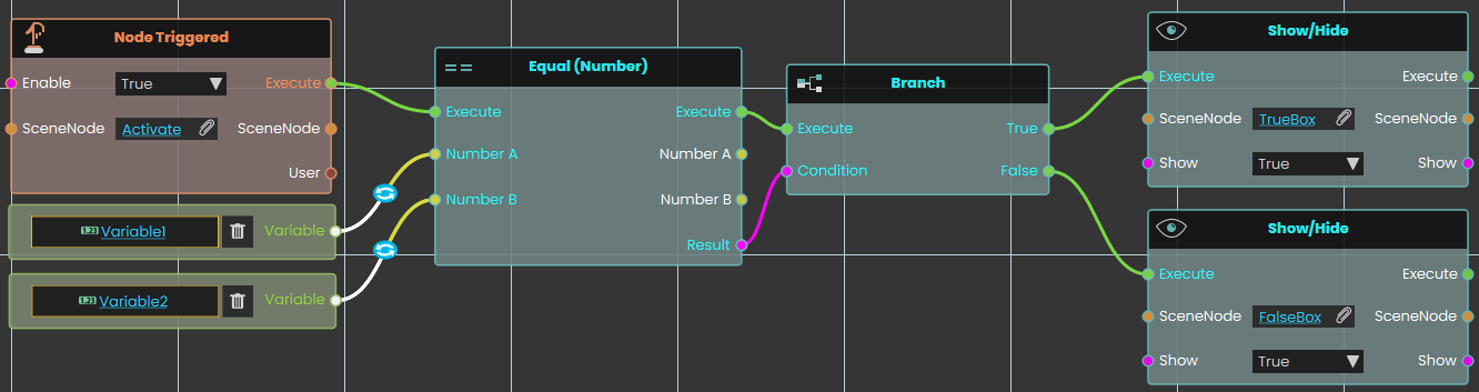
In this example, an Equal Response response is used to compare the value of Variable1 with the value of Variable2 once the user triggers the object named Activate. The result of the comparison can be acquired through the Result port. We have connected this Result port to the Branch node, and if the result of the branch is True, the TrueBox will show; if the result is False, the FalseBox will show.
 Greater (Number)
The Greater response enables the user to compare two values to determine if one is greater than the other by either typing in a numerical value in the Number A and Number B fields or by attaching a value or a variable node to those ports. Then once the response is executed, the result of the comparison can be acquired through the Result port.
Example
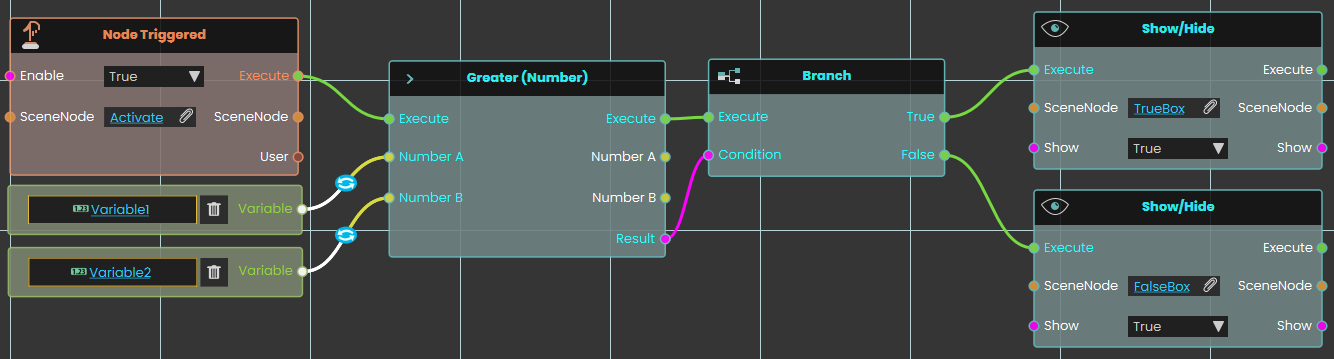
In this example, a Greater Response is used to compare the value of Variable1 with the value of Variable2 once the user triggers the object named Activate. The result of the comparison can be acquired through the Result port. We have connected this Result port to the Branch node, and if the result of the branch is True, the TrueBox will show; if the result is False, the FalseBox will show.
 Greater Or Equal (Number)
The Greater Or Equal response enables the user to compare two values to determine if one is greater than or equal to the other by either typing in a numerical value in the Number A and Number B fields or by attaching a value or a variable node to those ports. Then once the response is executed, the result of the comparison can be acquired through the Result port.
Example
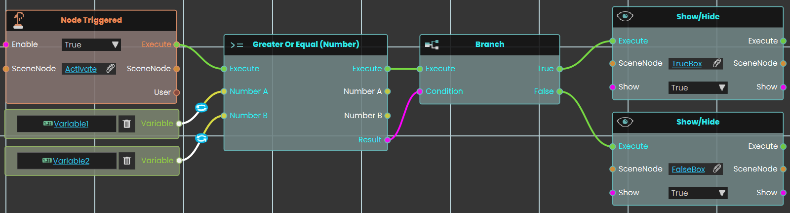
In this example, a Greater Or Equal Response is used to compare the value of Variable1 with the value of Variable2 once the user triggers the object named Activate. The result of the comparison can be acquired through the Result port. We have connected this Result port to the Branch node, and if the result of the branch is True, the TrueBox will show; if the result is False, the FalseBox will show.
 Less (Number)
The Less response enables the user to compare two values to determine if one is less than the other by either typing in a numerical value in the Number A and Number B fields or by attaching a value or a variable node to those ports. Then once the response is executed, the result of the comparison can be acquired through the Result port.
Example
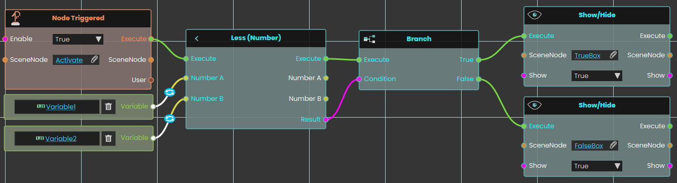
In this example, a Less is used to compare the value of Variable1 with the value of Variable2 once the user triggers the object named Activate. The result of the comparison can be acquired through the Result port. We have connected this Result port to the Branch node, and if the result of the branch is True, the TrueBox will show; if the result is False, the FalseBox will show.
 Less Or Equal (Number)
The Less Or Equal response enables the user to compare two values to determine if one is less than or equal to the other by either typing in a numerical value in the Number A and Number B fields or by attaching a value or a variable node to those ports. Then once the response is executed, the result of the comparison can be acquired through the Result port.
Example
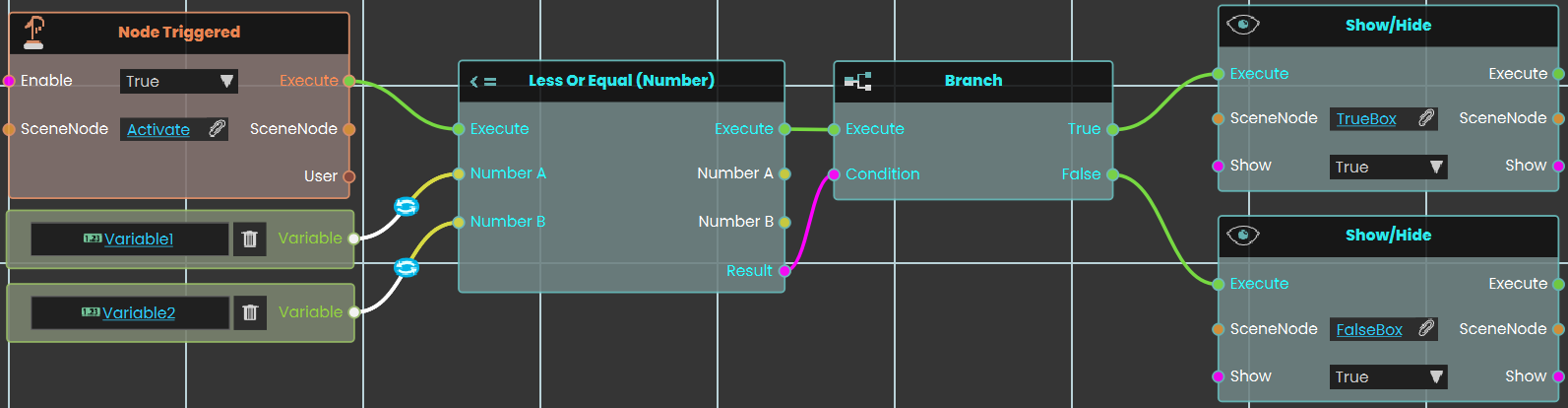
In this example, a Less is used to compare the value of Variable1 with the value of Variable2 once the user triggers the object named Activate. The result of the comparison can be acquired through the Result port. We have connected this Result port to the Branch node, and if the result of the branch is True, the TrueBox will show; if the result is False, the FalseBox will show.
 Not Equal (Number)
The Not Equal response enables the user to compare two values to determine if they are different by either typing in a numerical value in the Number A and Number B fields or by attaching a value or a variable node to those ports. Then once the response is executed, the result of the comparison can be acquired through the Result port.
Example

In this example, a Not Equal is used to compare the value of Variable1 with the value of Variable2 once the user triggers the object named Activate. The result of the comparison can be acquired through the Result port. We have connected this Result port to the Branch node, and if the result of the branch is True, the TrueBox will show; if the result is False, the FalseBox will show.
Data Types\Number\ Conversion
 Number To String
The Number to String node enables the user to convert a numerical value to a string by either typing in a numerical value in the Number field or by attaching a value or a variable node to that port. Then once the conversion is executed, the resulting string can be acquired through the String port.
String To Number
Turns a piece of text into a number you can do math with or compare.
What it does
This node reads the text you give it and hands back the matching number. For example, the text “42” comes back as the number 42, and “3.14” comes back as 3.14. Negative values like “-7” work too. This is handy when a value arrives as text—say from something the user typed—but you need it as a real number for calculations or comparisons.
The conversion only works when the text actually looks like a number. If you pass in something that isn’t a number, such as “hello”, you get no number back (an empty result). The original text is never changed—you simply get a new number value. This node is the reverse of the “Number To String” node on the same page.
Inputs
| Port | Type | What to connect |
|---|---|---|
| Execute | Trigger | Wire this from the previous node’s Execute output. |
| String | Text | The text you want turned into a number, such as “42” or “3.14”. |
Outputs
| Port | Type | What you get |
|---|---|---|
| Execute | Trigger | Fires once the node has finished. |
| Number | Number | The number that matches the text. If the text isn’t a number, you get an empty result. |
Example
| String input | “3.14” |
| Number output | 3.14 |
Tips
- Make sure the text really is a number. Extra characters like spaces or a currency sign can leave you with an empty result.
- If a value reaches you as text but you need to add, subtract, or compare it, run it through this node first.
Data Types\Number\ Expression
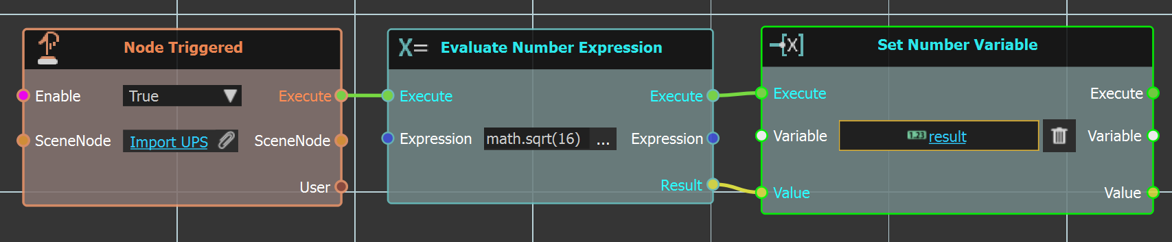
This node can evaluate an expression, then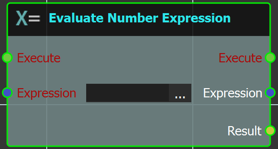
the result of this evaluation can be used to activate other responses.
Example
In the example below when the "Import_UPS" geometry is clicked "Evaluate Number Expression" is executed. The expression is simple math.sqrt(16), and the result is linked to the "Set Number Variable" node, in "result" variable. This variable is then linked to a "Variable Writer" to display it.
Data Types\Boolean\ Expression
This node can be used to generate values (true or false) that can
trigger events throughout the interactive experience.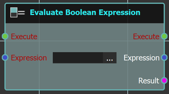
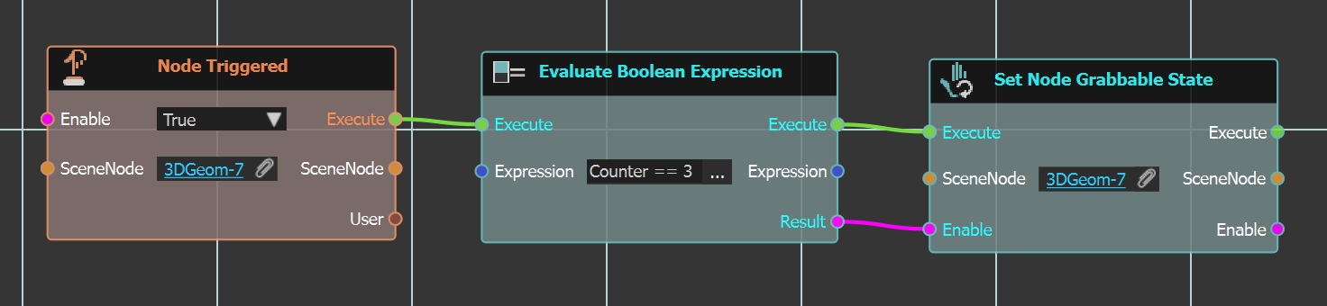
Example
In the example below when "3DGeom-7" is clicked, the expression in "Evaluate Boolean Expression" node is checked to execute the node after or not. In this case the expression is simple "==" which is true, so the "3DGeom-7" geometry will be set to Grabbable.
Data Types\Time
 Time Interval

This node calculates the time difference between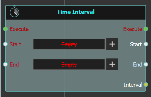
"Start", and "End" times. It stores the result in
an integer "Interval" out put.
 Update Time Variable

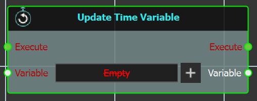
This node can be used to store time variables.
Example
The example below demonstrates the use of both time nodes above. In it the value of "inisial_time" variable is updated upon Scene Start. Then when "Box" geometry is clicked the value of "current_time" variable is updated. Then the "Time Interval" node is executed, where "result" variable is calculated as difference between both times.
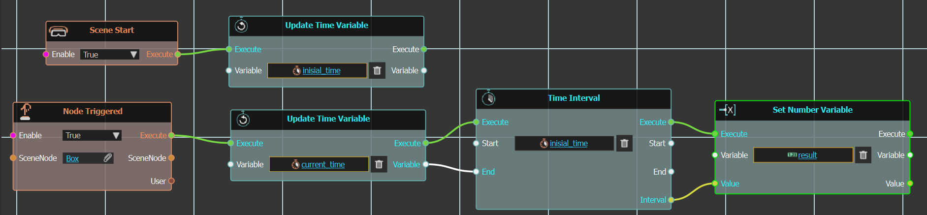
In the experience the "result" variable is connected to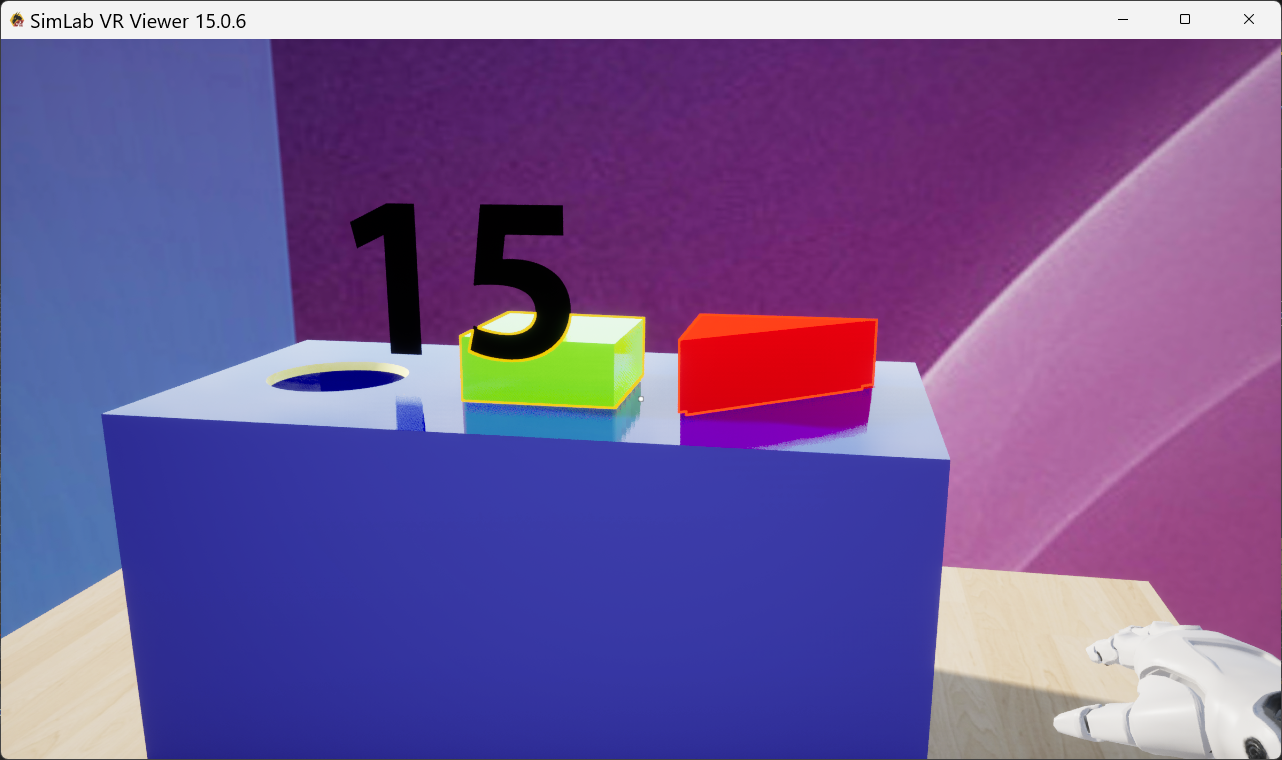
a Variable writer to display its value.
Scene State
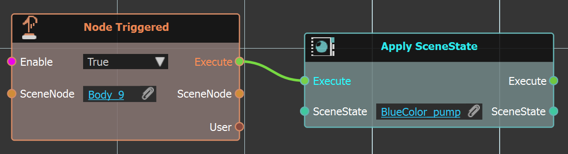
Apply SceneState
This node can be used to apply a scene state when an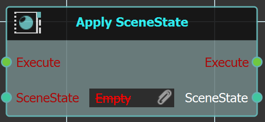
action is done in the 3D area.
Example
In the below example when "Body_9" is clicked the "BlueColor_pump" scene state is applied.
Find SceneState By Name
In complicated scenes with large number of scene 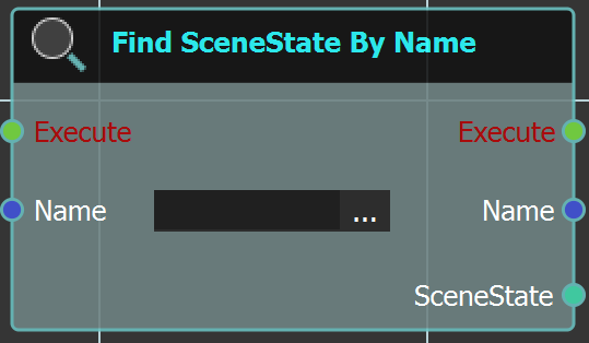
states, this node can come in handy. The user can use
this node to search for a scene state and then apply
it or do any action with it.
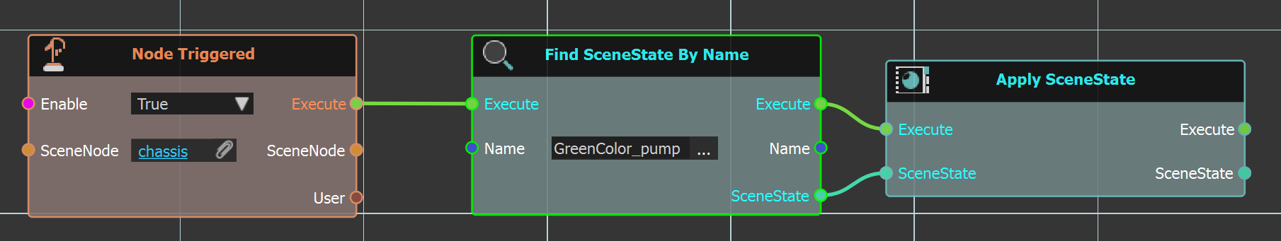
Example
In the example below this node is used to search for "GreenColor_pump" and then applied the scene state.
Sequence
Attach Sequence To
Creating sequences can be done from animating an object in the scene. This sequence can be attached to Hand or an Object in VR.
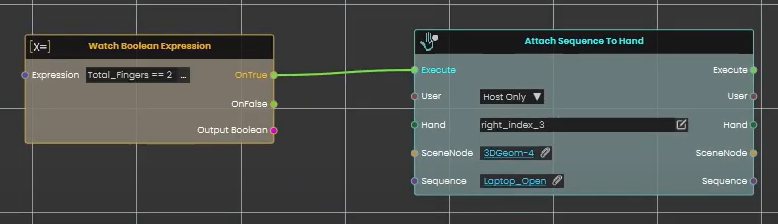
Hand
With sequences available in the Sequences Library, a sequence can be attached to the Hand in VR experience using this node in Dynamic Training Builder.
Example
Check this tutorial for the example below, where Boolean expressions were created and upon checking the Boolean Expression a sequence is attached to Hand.
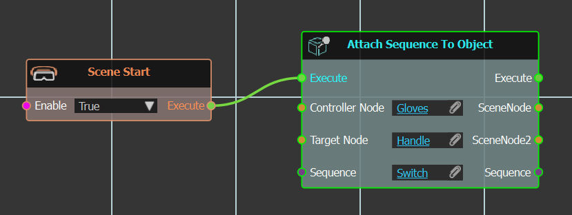
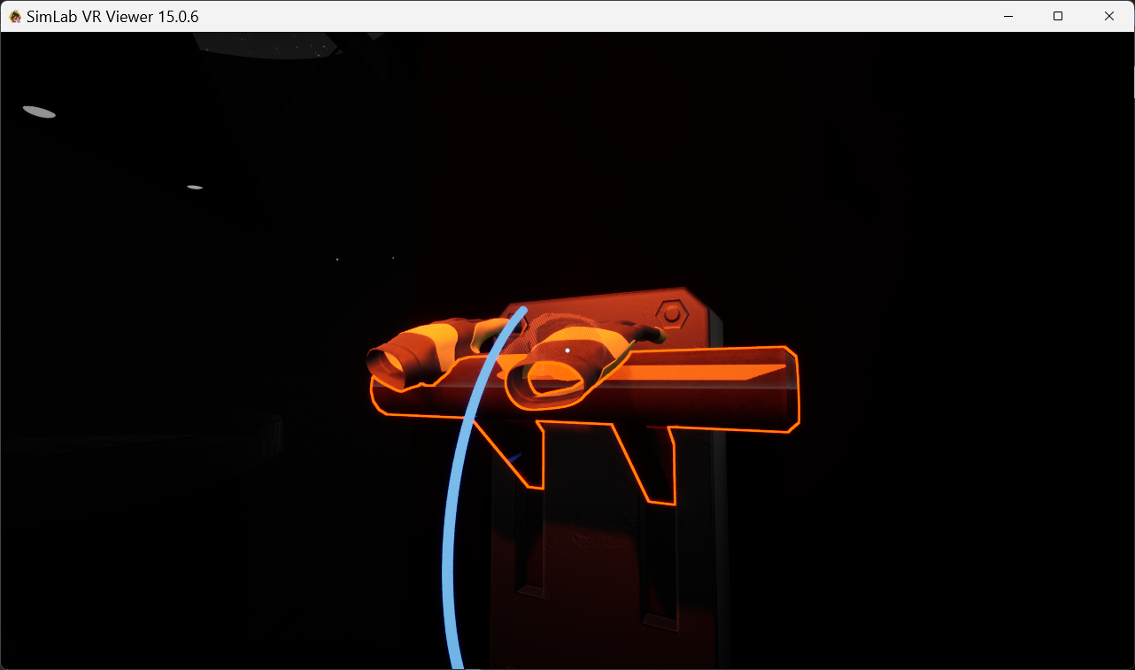
Object
This node can be used to connect a controller grabbable object to a sequence in VR.
Example
In the example below the "Switch" sequence is attached to "Handle" object, when Controller "Gloves" geometry moves it. In this example a simple grabbable sequence can do the job, but this is just to demonstrate use of this node.
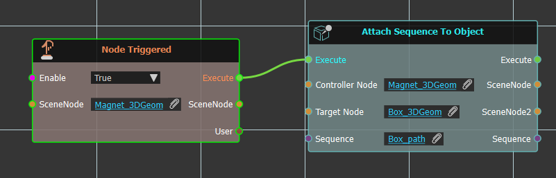
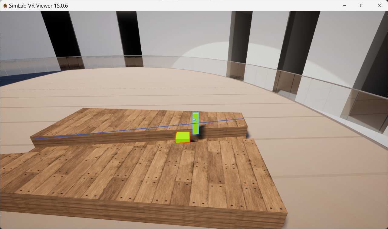
Example 2
In this example we have a path for a box to walk along being controlled by a magnet.
Detach Sequence
Releases a sequence that was attached to a scene object, so it is no longer linked to that object.
What it does
If you previously attached a sequence to an object in your scene, this node breaks that link. After it runs, the sequence stands on its own again and no longer follows the object it was attached to.
The sequence itself is not deleted or changed — only the attachment is removed. The same sequence comes back out of the node, so you can keep using it in the steps that follow.
Inputs
| Port | Type | What to connect |
|---|---|---|
| Execute | Trigger | Wire this from the previous node’s Execute output. |
| Sequence | Sequence | The sequence you want to detach — the one that is currently attached to a scene object. |
Outputs
| Port | Type | What you get |
|---|---|---|
| Execute | Trigger | Fires once the node has finished. |
| Sequence | Sequence | The same sequence, now detached — ready to use in the next steps. |
Example
| Sequence input | The Open Door sequence that was attached to the door handle |
| Sequence output | The same Open Door sequence, no longer linked to the handle |
Tips
- Use this to undo an earlier “Attach Sequence To” step when you no longer want the sequence to stay tied to that object.
Playback Controls
Used to control sequence behavior.
Continue
Same Direction
The selected sequence will continue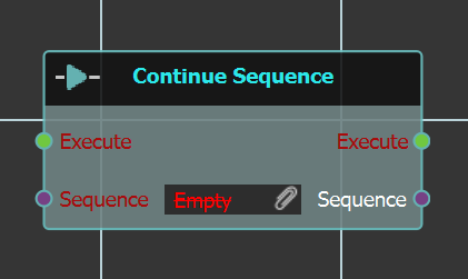
to play in the same direction.
Set Direction
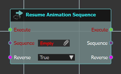 With this node the user can change the selected sequence direction, by selecting Reverse to True.
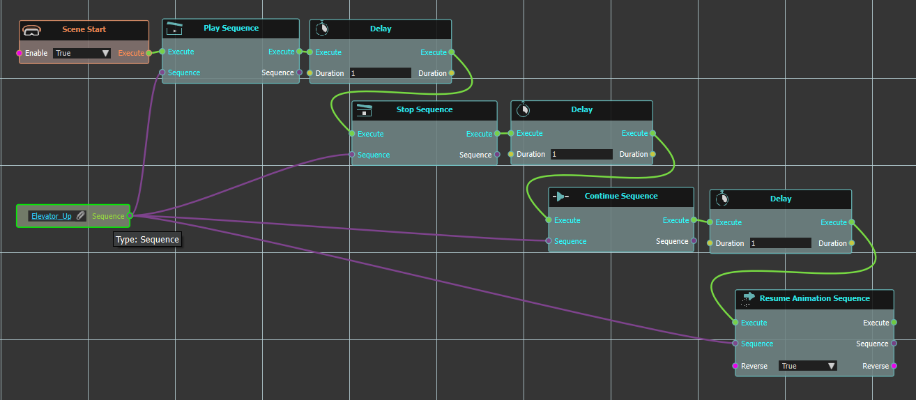
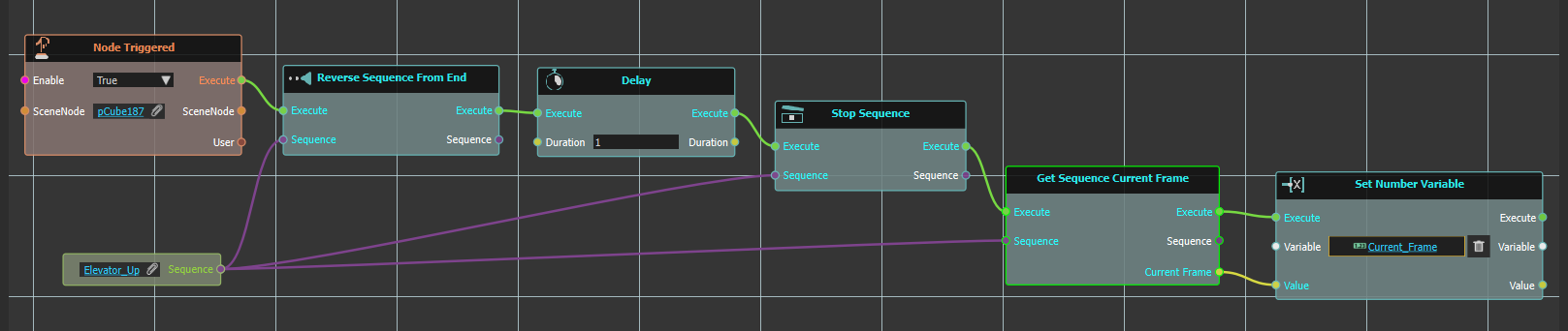
Example
In the below example a number of the above Playback Controls are used. Here on "Scene Start","Play Sequence" response is executed for "Elevator_Up" sequence. Followed by a 1 second "Delay", then "Stop Sequence" for another one second "Delay". Then the sequence is continued, followed by another "Delay" then "Resume Animation Sequence" from start.
Play
Play Sequence/Play Sequence From Start
Both controls will play animation sequence, one from current position, and the other -as the name implies- will play it from start.
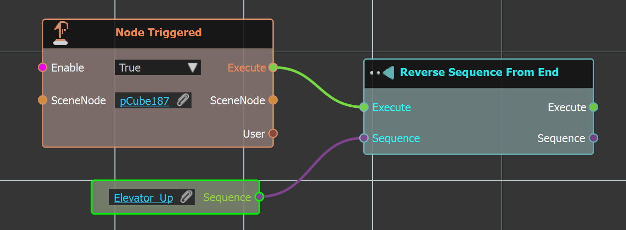
Reverse
Reverse
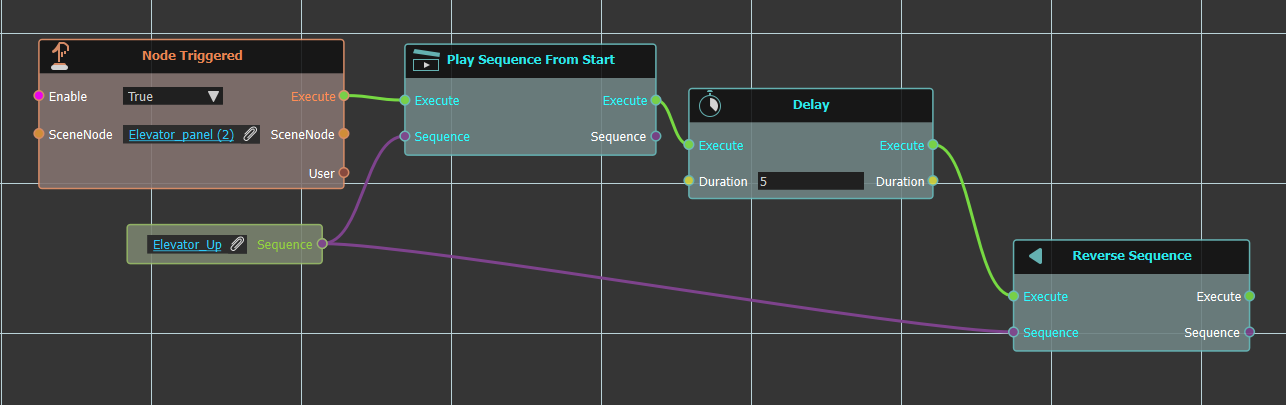
Reverse sequences starts the animation sequence in the reverse mode (from the last frame). The reverse control will start from the last frame not from the current (because it reverses the overall animation)
In the below example the "Elevator_Up" sequence upon clicking "Elevator_panel(2)" geometry will be played from start. So if the elevator at that time was at the top position, it would go down then -as the sequence implies- would go up, then wait for 5 seconds, then "Reverse Sequence" that is go down from last frame.
Reverse From End
This control will start the sequence from the end, even if it hasn’t been played yet.
Flip
Flip sequences flips current animation (that is, forward animation will be backward , backward animation will be forward). Think about it like we are opening a door and we pause the animation in the middle, flip control will return the door back from the current frame to original start position.
Stop
Stopes the animation sequence, as shown in examples presented in this section.
Playback Properties
Current Frame
Get Sequence Current Frame
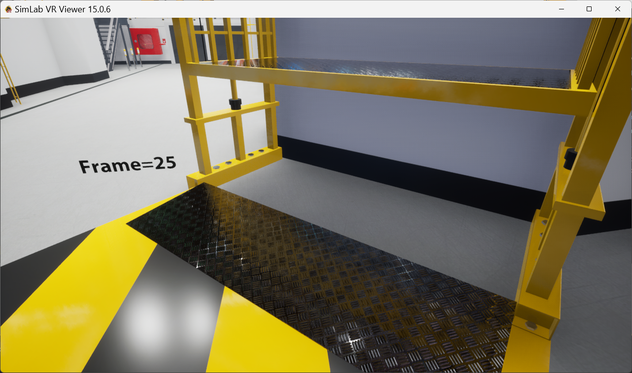
This node will get the value of the current sequence frame, the user can then use this value in any operation. In the example below the value of the current sequence frame is stored in "Current_Frame" variable, which is set to the "VR Variable Writer" in the scene to display its value.
Set Sequence Current Frame
If the user wants to go to a specific frame in the sequence this is the function to use. In the below example upon clicking node the sequence current frame is set to 10.
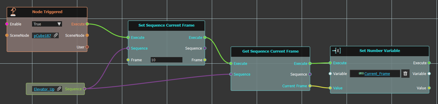
To show the result we got the valued of the current frame and assign it to "Current_Frame" variable that is displayed in the variable writer as shown below.
Full Range
This node can be used to calculate the full range of a sequence.
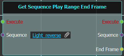
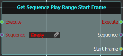
Get End
Gets and outputs the end frame of the selected 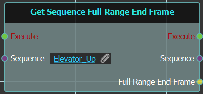
sequence, when triggered.
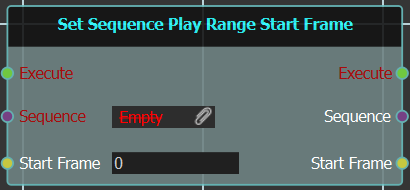
Get Start
Gets and outputs the start frame of the selected 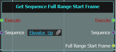
sequence, when triggered.
Looping
Sequences can be set to loop after finishing.
Get Sequence Looping
This node will get the looping status of the input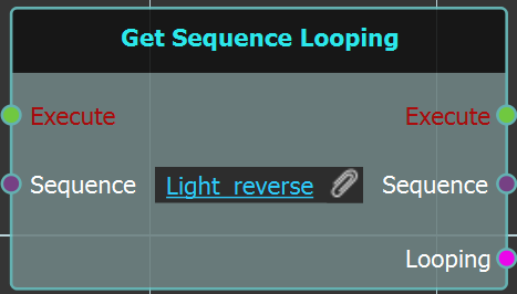
sequence, whether true or false.
Set Sequence Looping
This node will set the looping status for the input 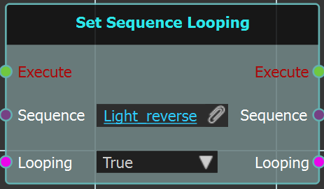
sequence to either true or false.
Play Range
Play Rate (Speed)
Swing
Is Playing
Is Reversing
Find By Name
User
 Show Mouse Cursor
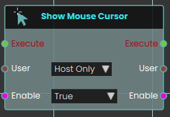
The Show Mouse Cursor node explicitly controls the visibility and functionality of the user's mouse pointer within the VR Viewer. When activated, the node checks the boolean Enable input for the specified User. Setting it to True displays the cursor on-screen, allowing the user to freely move it and click to interact with objects utilizing Node Triggered events. It is important to note that while this cursor mode is active, standard navigation is suspended—the user cannot walk or rotate their camera view until the node is activated again with the Enable input set to False, which hides the cursor and restores normal movement.
The Show Mouse Cursor mode is used for desktop/PC version of VR Viewer
Enable Gamepad Navigation
What it does
When you switch this on, the chosen user can use a connected gamepad to navigate the scene. Switch it off and gamepad navigation is turned off again for that user. You decide whether this applies just to the host or to everyone in the session.
The node only changes the gamepad setting for the user you pick — it doesn’t affect anything else about the scene. It also passes the same user and the on/off value straight through, so you can carry on with more steps right after it.
Inputs
| Port | Type | What to connect |
|---|---|---|
| Execute | Trigger | Wire this from the previous node’s Execute output. |
| User | User | Choose which participant this applies to: Host Only or All Users. You can also wire in a specific user from an earlier node. |
| Enable | True / false | Set this to true to turn gamepad navigation on, or false to turn it off. |
Outputs
| Port | Type | What you get |
|---|---|---|
| Execute | Trigger | Fires once the node has finished. |
| User | User | The same user, passed along so you can chain more user steps after this one. |
| Enable | True / false | The same on/off value you set, passed along for any later steps that need it. |
Example
| User input | All Users |
| Enable input | true |
| User output | The same user, ready for the next step |
| Enable output | true |
Tips
- Use the same node with Enable set to false later in your scene to turn gamepad navigation back off when it’s no longer needed.
Start QR Detection
Turns on QR code scanning for a participant so the scene can react when they point their view or device at a QR code.
What it does
When this node fires, the chosen participant starts looking for QR codes. From that moment on, whenever they aim at a QR code it can be picked up and used elsewhere in your scene. You can also choose whether an on-screen scanning panel appears to guide them, or whether detection happens quietly in the background.
This only switches scanning on — it doesn’t change the participant or the scene in any other way. The same participant is passed straight back out so you can connect more participant-related nodes after it.
Inputs
| Port | Type | What to connect |
|---|---|---|
| Execute | Trigger | Wire this from the previous node’s Execute output. |
| User | User | Choose who starts scanning: Host Only (just the main user) or All Users (everyone in the session). You can also wire in a participant from an earlier node. |
| Show UI? | True / false | Set to true to show the on-screen scanning panel that guides the participant, or false to scan quietly in the background. Defaults to true. |
Outputs
| Port | Type | What you get |
|---|---|---|
| Execute | Trigger | Fires once the node has finished. |
| User | User | The same participant you chose, passed along so you can connect more participant nodes after this one. |
Example
| User input | Host Only |
| Show UI? input | true |
| User output | The same participant, ready to pass on to the next node |
Tips
- Set Show UI? to
falsewhen you want scanning to feel seamless — for example, automatically recognizing a code the participant walks up to without a panel popping up. - This node only starts scanning. Use a matching stop node when you want the participant to stop looking for QR codes.
Stop QR Detection
Turns off QR code scanning for a participant, so the app stops looking for QR codes through their headset or device camera.
What it does
When you start QR detection, the chosen participant’s view keeps watching for QR codes in the real world around them. This node switches that watching back off. Once it runs, the app no longer scans for QR codes for that person, which is handy after they’ve scanned the code you needed, or when a part of your scene that relied on scanning is finished.
You pick who it applies to with the User input — just the host, or everyone. It only stops the scanning; it doesn’t undo anything that was already detected, and it has no effect if scanning wasn’t running for that participant. The same participant is passed straight through the User output, so you can carry on with more steps for that person.
Inputs
| Port | Type | What to connect |
|---|---|---|
| Execute | Trigger | Wire this from the previous node’s Execute output. |
| User | User | Choose who this applies to: Host Only (the default) or All Users. You can also wire in a participant passed along from an earlier user node. |
Outputs
| Port | Type | What you get |
|---|---|---|
| Execute | Trigger | Fires once the node has finished, so you can continue to the next step. |
| User | User | The same participant you chose, passed along so you can chain more user nodes after this one. |
Example
| User input | Host Only |
| User output | The same participant, ready for the next user node |
Tips
- Pair this with Start QR Detection: switch scanning on when you need a code read, then switch it off here once you’re done.
- Make sure the User choice matches the one you used to start scanning — if you started it for All Users, stop it for All Users too.
Show User Search Menu
Opens the user search menu on screen so a participant can look up and find other people in the session.
What it does
When this node runs, it brings up SimLab’s built-in user search menu for the participant you choose. From that menu the participant can search through the people in the session — handy in multi-user scenes where someone needs to locate a specific teammate.
You decide who sees the menu with the User input: either just the Host (Host Only) or everyone in the session (All Users). The node only opens the menu — it doesn’t change anything about the participant, and it passes that same user along on its output so you can connect more user-related nodes after it.
Inputs
| Port | Type | What to connect |
|---|---|---|
| Execute | Trigger | Wire this from the previous node’s Execute output to open the menu. |
| User | User | Chooses who the search menu opens for. Pick Host Only to show it just to the host, or All Users to show it to everyone in the session. |
Outputs
| Port | Type | What you get |
|---|---|---|
| Execute | Trigger | Fires once the menu has been opened, so you can continue to the next node. |
| User | User | Passes the same user along, so you can chain more user nodes after this one. |
Example
| User input | All Users |
| User output | The same participant, ready to pass to the next user node. |
User \ Controller
 Attach To Hand

The Attach to Hand node enables the user to attach objects to specific parts of the hand in a VR environment by selecting the desired hand part. This node allows for precise placement of objects, such as tools or items, enhancing interactivity within the VR Experience. Once the attachment is configured, the object will remain in the chosen part of the hand during interactions.
Example

In this example, an Attach to Hand node is used to attach a syringe to the index finger once the "Hand Enter Node" event is triggered. The syringe is attached to the specified part of the hand automatically when the event occurs, enabling interaction with the object in the VR environment.
 Detach From Hand

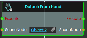
The Detach From Hand , detaches an object currently attached by the Attach To Hand response, so the object no more moves with the hand
 Trigger Beam

The Trigger Beam node enables the user to control the visibility of a beam coming out of the controller in the VR Experience, once the node is executed.
Example

In this example, a Trigger Beam node is used to hide the beam coming out of the controller once the object named Activate is triggered. When the event is triggered, the change is reflected during the VR Experience.
Enable Controller Vibration
Makes a participant’s VR controller buzz, so you can give them a physical nudge of feedback during a scene.
What it does
When this node runs, the chosen user’s controller vibrates in their hand. You pick which hand buzzes, how strong the buzz feels, how fast it pulses, and how long it lasts. This is great for confirming an action, drawing attention to something, or signalling a mistake.
It only triggers a buzz — it doesn’t change anything about the user or the scene. The same user is passed straight back out, so you can keep chaining more user nodes after it.
Inputs
| Port | Type | What to connect |
|---|---|---|
| Execute | Trigger | Wire this from the previous node’s Execute output. |
| User | User | Choose who feels the buzz. Pick Host Only to vibrate just the host’s controller, or All Users to vibrate everyone’s. You can also connect a User coming from an earlier node. |
| Hand | Choice | Which controller buzzes: Right, Left, or Both. Choosing Both vibrates both controllers at once. |
| Strength | Choice | How intense the buzz feels: High, Medium, or Low. |
| Frequency | Choice | How fast the buzz pulses: High, Medium, or Low. |
| Duration | Number | How long the buzz lasts, in seconds (0 or more). For example, 1 is a one-second buzz. |
Outputs
| Port | Type | What you get |
|---|---|---|
| Execute | Trigger | Fires once the node has finished. |
| User | User | The same user you chose, passed along so you can connect more user nodes after this one. |
Example
| User input | Host Only |
| Hand input | Right |
| Strength input | High |
| Frequency input | Medium |
| Duration input | 1 (a one-second buzz) |
| User output | The host, ready to pass on to the next node |
Tips
- Use a short, strong buzz to confirm a correct action, and a longer or gentler one to warn of a mistake.
- Pick
Bothfor the Hand when you want a buzz the participant can’t miss.
Disable Controller Vibration
Turns off the buzzing (haptic feedback) in a participant’s VR controller.
What it does
This node stops the vibration in the chosen hand’s controller for the user you pick. Use it to silence the controller after a buzz, or to make sure a controller stays quiet during a particular part of your scene.
You choose which participant it affects (the host only, or everyone) and which hand to quiet down — the right controller, the left controller, or both. It only controls the vibration; it doesn’t change anything else about the controller or the user, and the same user is passed straight back out so you can connect more user nodes after it.
Inputs
| Port | Type | What to connect |
|---|---|---|
| Execute | Trigger | Wire this from the previous node’s Execute output to run the node. |
| User | User | Chooses which participant to act on. Pick Host Only to quiet just the main user’s controller, or All Users to quiet everyone’s. |
| Hand | Choice | Which controller to turn off the vibration on: Right, Left, or Both. |
Outputs
| Port | Type | What you get |
|---|---|---|
| Execute | Trigger | Fires once the vibration has been turned off, so you can continue to the next node. |
| User | User | The same user you chose, passed along so you can chain more user nodes after this one. |
Example
| User input | Host Only |
| Hand input | Both |
| User output | The same host user, ready to connect to the next node |
Tips
- Pair this with the Enable Controller Vibration node: turn the buzzing on for a moment of feedback, then use this node to switch it back off.
- Choose Both when you want both controllers to stop at the same time, rather than adding two separate nodes for the left and right hands.
User \ Transform
 Get User Rotation

The Get User Rotation response enables the user to get the values of the User's head rotation, and allows them to store the values of the Pitch, Yaw and Roll and the results can be acquired through their output ports.
Example

In this example, a Get User Rotation response is used to check the head rotation angles (Pitch, Yaw and Roll). Once the object named Activate is triggered, the head rotation values (Pitch, Yaw, Roll) of the user with attribute InBuilding and Value Yes are calculated and stored in the variables named Pitch, Yaw, Roll, in order to use them in the VR Experience.
Get User Location
Finds out where a user is currently standing in your scene and gives you their position as three numbers.
What it does
This node reads a user’s current position in the scene and hands back the three coordinates that describe it: X, Y, and Z, measured in meters. You can use these numbers to check where someone is, compare it to another spot, or feed it into other nodes.
It only reads the position — it does not move the user or change anything about them. The user stays exactly where they are.
Inputs
| Port | Type | What to connect |
|---|---|---|
| Execute | Trigger | Wire this from the previous node’s Execute output. |
| User | User | The user whose position you want to read. A dropdown lets you choose Host Only (the default — the main user) or All Users, which reads the position of everyone in a shared collaboration session. |
Outputs
| Port | Type | What you get |
|---|---|---|
| Execute | Trigger | Fires once the node has finished. |
| User | User | The same user you put in, passed straight through so you can chain it into more user nodes. |
| X | Number | The user’s position along the X axis, in meters. |
| Y | Number | The user’s position along the Y axis, in meters. |
| Z | Number | The user’s position along the Z axis, in meters. |
Example
| User input | Host Only |
| X output | 2.5 |
| Y output | 1.7 |
| Z output | -4.0 |
Tips
- Pair this with Get User Rotation when you need both where the user is standing and which way they are facing.
- Choose All Users only in a shared collaboration session; for a single-user scene, Host Only is what you want.
 Teleport To Camera

The Teleport To Camera node enables the user to teleport to a new location by assigning a camera in the CameraNode field. Once the teleportation is executed, the user is moved to the position and orientation defined by the specified camera, the user can also decide whether this teleportation affect the host only or all the user in the experience (in case of collaboration).
Example

In this example, a Teleport To Camera response is used to move the user to a new location once the object named Activate is triggered. When triggered, the sound named Teleport_Sound will play, and the user will be teleported to the location of the camera assigned in the Teleport To Camera node.
 Attach User

The Attach User node allows users to attach the user to specific objects within the VR Experience. This node ensures that the user moves along with the object, providing an immersive experience where the user is fixed to the selected object throughout the VR environment, this can be decided to affect only the host or all user (in case of collaboration).
Example
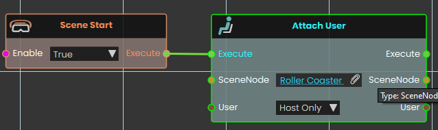
In this example, the Attach User node is used to attach the user to a roller coaster at the start of the scene. When the scene starts, the user will be fixed to the roller coaster, moving along with it as it travels through the environment, providing an immersive experience.
 Detach User

The Detach User node allows users to detach from an object within the VR Experience. This node provides a straightforward way to release the user from an object they were attached to, ensuring they regain control of their own movement and are no longer fixed to the selected object or location.
Example
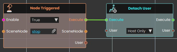
In this example, the Detach User node is used to detach the user from a roller coaster when the roller coaster's animation ends. Once the animation is complete, the user will be released from the roller coaster.
User \ Gadget
 Equip To User

The Equip to User Node enables the user to equip or unequip gadgets, adjacent objects, or HUD elements to the user within the VR environment. This node enhances interactivity by enabling users to interact directly with various items and interface elements as part of their virtual experience.
Example

In this example, the Equip to User Node is used to equip a gun controller to the user. Select the gun object, then assign it to the controller by clicking on the plus icon in the User Gadget window.

To activate the gun gadget, press the right grip button then the gun will be attached to the User's controller in the VR environment.
User \ Attributes
Every user in your experience can carry extra pieces of information called attributes — small named values you attach to a user and read back later. Attributes can also be grouped into named categories, which lets one user keep separate attributes that share a name. The nodes on this page let you add, read, check for, and remove attributes on a user, both on their own and inside a category.
Reading an attribute never changes it; setting or removing one changes only that single attribute and leaves everything else about the user untouched.
Get a user attribute
Get User Attribute (Number)
Reads a named attribute from a user and gives it back as a number.
What it does
Every user in your session can carry extra pieces of information called attributes, each one saved under a name you choose. This node looks for the attribute called the name you provide on the user you connect and hands its value back as a number. It only reads the user — it does not change the user or the attribute in any way.
The attribute should already exist and hold a number. If it is missing, or what is stored cannot be read as a number, the node stops with an error instead of giving you a result — so check with User Has Attribute first if you are not sure.
Inputs
| Port | Type | What to connect |
|---|---|---|
| Execute | Trigger | Wire this from the previous node’s Execute output. |
| User | User | The user you want to read the attribute from. If you leave this port unconnected, you can pick an option on the node itself: Host Only (the default) or All Users. |
| Attribute Name | Text | The name of the attribute you want to read. |
Outputs
| Port | Type | What you get |
|---|---|---|
| Execute | Trigger | Fires once the node has finished. |
| User | User | The same user you connected, passed straight through so you can keep using it. |
| Attribute Name | Text | The attribute name you provided, passed through. |
| Value | Number | The number stored in the attribute. |
Example
| User input | the <Trainee01> user |
| Attribute Name input | score |
| Value output | 85 |
Get User Attribute (Boolean)
Reads a named attribute from a user and gives it back as a true / false value.
What it does
Every user in your session can carry extra pieces of information called attributes, each one saved under a name you choose. This node looks for the attribute called the name you provide on the user you connect and hands its value back as a true / false value. It only reads the user — it does not change the user or the attribute in any way.
The attribute should already exist and hold a true / false value. If it is missing, or what is stored cannot be read as a true / false value, the node stops with an error instead of giving you a result — so check with User Has Attribute first if you are not sure.
Saved values of true, yes or on are read as true, and false, no or off are read as false.
Inputs
| Port | Type | What to connect |
|---|---|---|
| Execute | Trigger | Wire this from the previous node’s Execute output. |
| User | User | The user you want to read the attribute from. If you leave this port unconnected, you can pick an option on the node itself: Host Only (the default) or All Users. |
| Attribute Name | Text | The name of the attribute you want to read. |
Outputs
| Port | Type | What you get |
|---|---|---|
| Execute | Trigger | Fires once the node has finished. |
| User | User | The same user you connected, passed straight through so you can keep using it. |
| Attribute Name | Text | The attribute name you provided, passed through. |
| Result | True / false | The true / false value stored in the attribute. |
Example
| User input | the <Trainee01> user |
| Attribute Name input | certified |
| Result output | true |
Get User Attribute (SceneNode)
Reads a named attribute from a user and gives it back as a scene node.
What it does
Every user in your session can carry extra pieces of information called attributes, each one saved under a name you choose. This node looks for the attribute called the name you provide on the user you connect and hands its value back as a scene node. It only reads the user — it does not change the user or the attribute in any way.
The attribute should already exist and hold a scene node. If it is missing, you get an empty result rather than an error, so it is still worth checking with User Has Attribute first.
Inputs
| Port | Type | What to connect |
|---|---|---|
| Execute | Trigger | Wire this from the previous node’s Execute output. |
| User | User | The user you want to read the attribute from. |
| Attribute Name | Text | The name of the attribute you want to read. |
Outputs
| Port | Type | What you get |
|---|---|---|
| Execute | Trigger | Fires once the node has finished. |
| User | User | The same user you connected, passed straight through so you can keep using it. |
| Attribute Name | Text | The attribute name you provided, passed through. |
| Result | Scene node | The scene node stored in the attribute. |
Example
| User input | the <Trainee01> user |
| Attribute Name input | assignedStation |
| Result output | <WeldingStation> |
Get User Attribute (SceneState)
Reads a named attribute from a user and gives it back as a scene state.
What it does
Every user in your session can carry extra pieces of information called attributes, each one saved under a name you choose. This node looks for the attribute called the name you provide on the user you connect and hands its value back as a scene state. It only reads the user — it does not change the user or the attribute in any way.
The attribute should already exist and hold a scene state. If it is missing, you get an empty result rather than an error, so it is still worth checking with User Has Attribute first.
Inputs
| Port | Type | What to connect |
|---|---|---|
| Execute | Trigger | Wire this from the previous node’s Execute output. |
| User | User | The user you want to read the attribute from. |
| Attribute Name | Text | The name of the attribute you want to read. |
Outputs
| Port | Type | What you get |
|---|---|---|
| Execute | Trigger | Fires once the node has finished. |
| User | User | The same user you connected, passed straight through so you can keep using it. |
| Attribute Name | Text | The attribute name you provided, passed through. |
| Result | Scene state | The scene state stored in the attribute. |
Example
| User input | the <Trainee01> user |
| Attribute Name input | checkpoint |
| Result output | <Checkpoint2> |
Get User Attribute (Sequence)
Reads a named attribute from a user and gives it back as a sequence.
What it does
Every user in your session can carry extra pieces of information called attributes, each one saved under a name you choose. This node looks for the attribute called the name you provide on the user you connect and hands its value back as a sequence. It only reads the user — it does not change the user or the attribute in any way.
The attribute should already exist and hold a sequence. If it is missing, you get an empty result rather than an error, so it is still worth checking with User Has Attribute first.
Inputs
| Port | Type | What to connect |
|---|---|---|
| Execute | Trigger | Wire this from the previous node’s Execute output. |
| User | User | The user you want to read the attribute from. |
| Attribute Name | Text | The name of the attribute you want to read. |
Outputs
| Port | Type | What you get |
|---|---|---|
| Execute | Trigger | Fires once the node has finished. |
| User | User | The same user you connected, passed straight through so you can keep using it. |
| Attribute Name | Text | The attribute name you provided, passed through. |
| Result | Sequence | The sequence stored in the attribute. |
Example
| User input | the <Trainee01> user |
| Attribute Name input | introSequence |
| Result output | <SafetyBriefing> |
Set a user attribute
 Set User Attribute (String)

The Set User Attribute response enables user to set a value to an attribute by either typing in a string value in the value field or by attaching a value or a variable node to that port. Then once the response is executed, the variable value can be acquired through the Value port.
Example

In this example, we added a String User Attribute called it Indoor with the value No

Once the user enters the object named Building, the Indoor attribute's value will be set to Yes, then when the object named Teleport Button is triggered, the user(s) with the attribute named Indoor and the value Yes will be teleported to the Outside CameraNode location.
Set User Attribute (Number)
Saves a number onto a user as a named attribute.
What it does
Every user in your session can carry extra pieces of information called attributes, each one saved under a name you choose. This node attaches the attribute called the name you provide to the user you connect and stores a number in it. If the user already has an attribute with that name, its value is replaced; if not, the attribute is created.
The value you provide is also sent straight back out, so you can keep using it further along.
Inputs
| Port | Type | What to connect |
|---|---|---|
| Execute | Trigger | Wire this from the previous node’s Execute output. |
| User | User | The user you want to add or change the attribute on. If you leave this port unconnected, you can pick an option on the node itself — Host Only (the default) or All Users, which saves the attribute on every user in the session. |
| Attribute Name | Text | The name to save the attribute under. |
| Value | Number | The number to store. |
Outputs
| Port | Type | What you get |
|---|---|---|
| Execute | Trigger | Fires once the node has finished. |
| User | User | The same user you connected, passed straight through so you can keep using it. |
| Attribute Name | Text | The attribute name you provided, passed through. |
| Value | Number | The same value you stored, passed through. |
Example
| User input | the <Trainee01> user |
| Attribute Name input | score |
| Value input | 85 |
Set User Attribute (Boolean)
Saves a true / false value onto a user as a named attribute.
What it does
Every user in your session can carry extra pieces of information called attributes, each one saved under a name you choose. This node attaches the attribute called the name you provide to the user you choose and stores a true / false value in it. If the user already has an attribute with that name, its value is replaced; if not, the attribute is created.
The value you provide is also sent straight back out, so you can keep using it further along.
Inputs
| Port | Type | What to connect |
|---|---|---|
| Execute | Trigger | Wire this from the previous node’s Execute output. |
| User | User | The user you want to add or change the attribute on. If you leave this port unconnected, you can pick an option on the node itself — Host Only (the default) or All Users, which saves the attribute on every user in the session. |
| Attribute Name | Text | The name to save the attribute under. |
| Value | True / false | The true / false value to store. |
Outputs
| Port | Type | What you get |
|---|---|---|
| Execute | Trigger | Fires once the node has finished. |
| User | User | The same user you connected, passed straight through so you can keep using it. |
| Attribute Name | Text | The attribute name you provided, passed through. |
| Value | True / false | The same value you stored, passed through. |
Example
| User input | the <Trainee01> user |
| Attribute Name input | certified |
| Value input | true |
Set User Attribute (SceneNode)
Saves a scene node onto a user as a named attribute.
What it does
Every user in your session can carry extra pieces of information called attributes, each one saved under a name you choose. This node attaches the attribute called the name you provide to the user you connect and stores a scene node in it. If the user already has an attribute with that name, its value is replaced; if not, the attribute is created.
The value you provide is also sent straight back out, so you can keep using it further along.
Inputs
| Port | Type | What to connect |
|---|---|---|
| Execute | Trigger | Wire this from the previous node’s Execute output. |
| User | User | The user you want to add or change the attribute on. |
| Attribute Name | Text | The name to save the attribute under. |
| Value | Scene node | The scene node to save a link to. |
Outputs
| Port | Type | What you get |
|---|---|---|
| Execute | Trigger | Fires once the node has finished. |
| User | User | The same user you connected, passed straight through so you can keep using it. |
| Attribute Name | Text | The attribute name you provided, passed through. |
| Value | Scene node | The same value you stored, passed through. |
Example
| User input | the <Trainee01> user |
| Attribute Name input | assignedStation |
| Value input | the <WeldingStation> object |
Set User Attribute (SceneState)
Saves a scene state onto a user as a named attribute.
What it does
Every user in your session can carry extra pieces of information called attributes, each one saved under a name you choose. This node attaches the attribute called the name you provide to the user you connect and stores a scene state in it. If the user already has an attribute with that name, its value is replaced; if not, the attribute is created.
The value you provide is also sent straight back out, so you can keep using it further along.
Inputs
| Port | Type | What to connect |
|---|---|---|
| Execute | Trigger | Wire this from the previous node’s Execute output. |
| User | User | The user you want to add or change the attribute on. |
| Attribute Name | Text | The name to save the attribute under. |
| Value | Scene state | The scene state to save a link to. |
Outputs
| Port | Type | What you get |
|---|---|---|
| Execute | Trigger | Fires once the node has finished. |
| User | User | The same user you connected, passed straight through so you can keep using it. |
| Attribute Name | Text | The attribute name you provided, passed through. |
| Value | Scene state | The same value you stored, passed through. |
Example
| User input | the <Trainee01> user |
| Attribute Name input | checkpoint |
| Value input | <Checkpoint2> |
Set User Attribute (Sequence)
Saves a sequence onto a user as a named attribute.
What it does
Every user in your session can carry extra pieces of information called attributes, each one saved under a name you choose. This node attaches the attribute called the name you provide to the user you connect and stores a sequence in it. If the user already has an attribute with that name, its value is replaced; if not, the attribute is created.
The value you provide is also sent straight back out, so you can keep using it further along.
Inputs
| Port | Type | What to connect |
|---|---|---|
| Execute | Trigger | Wire this from the previous node’s Execute output. |
| User | User | The user you want to add or change the attribute on. |
| Attribute Name | Text | The name to save the attribute under. |
| Value | Sequence | The sequence to save a link to. |
Outputs
| Port | Type | What you get |
|---|---|---|
| Execute | Trigger | Fires once the node has finished. |
| User | User | The same user you connected, passed straight through so you can keep using it. |
| Attribute Name | Text | The attribute name you provided, passed through. |
| Value | Sequence | The same value you stored, passed through. |
Example
| User input | the <Trainee01> user |
| Attribute Name input | introSequence |
| Value input | <SafetyBriefing> |
Check or remove a user attribute
User Has Attribute
Checks whether a user has an attribute with a given name.
What it does
This node looks at the user you connect and tells you whether they already have an attribute saved under the name you provide. You get back true if they do and false if they do not. It only checks — nothing on the user is changed.
It is handy to run before reading or changing an attribute, to be sure it is there.
Inputs
| Port | Type | What to connect |
|---|---|---|
| Execute | Trigger | Wire this from the previous node’s Execute output. |
| User | User | The user you want to check. |
| Attribute Name | Text | The name of the attribute to look for. |
Outputs
| Port | Type | What you get |
|---|---|---|
| Execute | Trigger | Fires once the node has finished. |
| User | User | The same user you connected, passed straight through so you can keep using it. |
| Attribute Name | Text | The attribute name you provided, passed through. |
| Result | True / false | True if the attribute exists, otherwise false. |
Example
| User input | the <Trainee01> user |
| Attribute Name input | certified |
| Result output | true — the attribute exists |
Remove User Attribute
Deletes a named attribute from a user.
What it does
This node removes the attribute saved under the name you provide from the user you connect. That one attribute and its value are deleted from the user; everything else about the user stays the same.
If the user has no attribute with that name, nothing happens.
Inputs
| Port | Type | What to connect |
|---|---|---|
| Execute | Trigger | Wire this from the previous node’s Execute output. |
| User | User | The user you want to remove the attribute from. |
| Attribute Name | Text | The name of the attribute to remove. |
Outputs
| Port | Type | What you get |
|---|---|---|
| Execute | Trigger | Fires once the node has finished. |
| User | User | The same user you connected, passed straight through so you can keep using it. |
| Attribute Name | Text | The attribute name you provided, passed through. |
Example
| User input | the <Trainee01> user |
| Attribute Name input | tempNote |
Get a user attribute in a category
Get User Attribute in Category (String)
Reads a named attribute kept in a category on a user and gives it back as a piece of text.
What it does
Every user in your session can carry extra pieces of information called attributes, each one saved under a name you choose. Attributes can also be grouped into named categories, so a single user can keep separate attributes that share a name in different categories. This node looks for the attribute called the name you provide inside the category you name, on the user you connect and hands its value back as a piece of text. It only reads the user — it does not change the user or the attribute in any way.
The attribute should already exist and hold text. If it is missing, you get an empty result rather than an error, so it is still worth checking with User Has Attribute In Category first.
Inputs
| Port | Type | What to connect |
|---|---|---|
| Execute | Trigger | Wire this from the previous node’s Execute output. |
| User | User | The user you want to read the attribute from. |
| Attribute Name | Text | The name of the attribute you want to read. |
| Category | Text | The name of the category the attribute is kept in. |
Outputs
| Port | Type | What you get |
|---|---|---|
| Execute | Trigger | Fires once the node has finished. |
| User | User | The same user you connected, passed straight through so you can keep using it. |
| Attribute Name | Text | The attribute name you provided, passed through. |
| Category | Text | The category name you provided, passed through. |
| Result | Text | The text stored in the attribute. |
Example
| User input | the <Trainee01> user |
| Attribute Name input | role |
| Category input | Training |
| Result output | Safety Officer |
Get User Attribute in Category (Number)
Reads a named attribute kept in a category on a user and gives it back as a number.
What it does
Every user in your session can carry extra pieces of information called attributes, each one saved under a name you choose. Attributes can also be grouped into named categories, so a single user can keep separate attributes that share a name in different categories. This node looks for the attribute called the name you provide inside the category you name, on the user you connect and hands its value back as a number. It only reads the user — it does not change the user or the attribute in any way.
The attribute should already exist and hold a number. If it is missing, or what is stored cannot be read as a number, the node stops with an error instead of giving you a result — so check with User Has Attribute In Category first if you are not sure.
Inputs
| Port | Type | What to connect |
|---|---|---|
| Execute | Trigger | Wire this from the previous node’s Execute output. |
| User | User | The user you want to read the attribute from. |
| Attribute Name | Text | The name of the attribute you want to read. |
| Category | Text | The name of the category the attribute is kept in. |
Outputs
| Port | Type | What you get |
|---|---|---|
| Execute | Trigger | Fires once the node has finished. |
| User | User | The same user you connected, passed straight through so you can keep using it. |
| Attribute Name | Text | The attribute name you provided, passed through. |
| Category | Text | The category name you provided, passed through. |
| Result | Number | The number stored in the attribute. |
Example
| User input | the <Trainee01> user |
| Attribute Name input | score |
| Category input | Training |
| Result output | 85 |
Get User Attribute in Category (Boolean)
Reads a named attribute kept in a category on a user and gives it back as a true / false value.
What it does
Every user in your session can carry extra pieces of information called attributes, each one saved under a name you choose. Attributes can also be grouped into named categories, so a single user can keep separate attributes that share a name in different categories. This node looks for the attribute called the name you provide inside the category you name, on the user you connect and hands its value back as a true / false value. It only reads the user — it does not change the user or the attribute in any way.
The attribute should already exist and hold a true / false value. If it is missing, or what is stored cannot be read as a true / false value, the node stops with an error instead of giving you a result — so check with User Has Attribute In Category first if you are not sure.
Saved values of true, yes or on are read as true, and false, no or off are read as false.
Inputs
| Port | Type | What to connect |
|---|---|---|
| Execute | Trigger | Wire this from the previous node’s Execute output. |
| User | User | The user you want to read the attribute from. |
| Attribute Name | Text | The name of the attribute you want to read. |
| Category | Text | The name of the category the attribute is kept in. |
Outputs
| Port | Type | What you get |
|---|---|---|
| Execute | Trigger | Fires once the node has finished. |
| User | User | The same user you connected, passed straight through so you can keep using it. |
| Attribute Name | Text | The attribute name you provided, passed through. |
| Category | Text | The category name you provided, passed through. |
| Result | True / false | The true / false value stored in the attribute. |
Example
| User input | the <Trainee01> user |
| Attribute Name input | certified |
| Category input | Training |
| Result output | true |
Get User Attribute in Category (SceneNode)
Reads a named attribute kept in a category on a user and gives it back as a scene node.
What it does
Every user in your session can carry extra pieces of information called attributes, each one saved under a name you choose. Attributes can also be grouped into named categories, so a single user can keep separate attributes that share a name in different categories. This node looks for the attribute called the name you provide inside the category you name, on the user you connect and hands its value back as a scene node. It only reads the user — it does not change the user or the attribute in any way.
The attribute should already exist and hold a scene node. If it is missing, you get an empty result rather than an error, so it is still worth checking with User Has Attribute In Category first.
Inputs
| Port | Type | What to connect |
|---|---|---|
| Execute | Trigger | Wire this from the previous node’s Execute output. |
| User | User | The user you want to read the attribute from. |
| Attribute Name | Text | The name of the attribute you want to read. |
| Category | Text | The name of the category the attribute is kept in. |
Outputs
| Port | Type | What you get |
|---|---|---|
| Execute | Trigger | Fires once the node has finished. |
| User | User | The same user you connected, passed straight through so you can keep using it. |
| Attribute Name | Text | The attribute name you provided, passed through. |
| Category | Text | The category name you provided, passed through. |
| Result | Scene node | The scene node stored in the attribute. |
Example
| User input | the <Trainee01> user |
| Attribute Name input | assignedStation |
| Category input | Training |
| Result output | the <WeldingStation> object |
Get User Attribute in Category (SceneState)
Reads a named attribute kept in a category on a user and gives it back as a scene state.
What it does
Every user in your session can carry extra pieces of information called attributes, each one saved under a name you choose. Attributes can also be grouped into named categories, so a single user can keep separate attributes that share a name in different categories. This node looks for the attribute called the name you provide inside the category you name, on the user you connect and hands its value back as a scene state. It only reads the user — it does not change the user or the attribute in any way.
The attribute should already exist and hold a scene state. If it is missing, you get an empty result rather than an error, so it is still worth checking with User Has Attribute In Category first.
Inputs
| Port | Type | What to connect |
|---|---|---|
| Execute | Trigger | Wire this from the previous node’s Execute output. |
| User | User | The user you want to read the attribute from. |
| Attribute Name | Text | The name of the attribute you want to read. |
| Category | Text | The name of the category the attribute is kept in. |
Outputs
| Port | Type | What you get |
|---|---|---|
| Execute | Trigger | Fires once the node has finished. |
| User | User | The same user you connected, passed straight through so you can keep using it. |
| Attribute Name | Text | The attribute name you provided, passed through. |
| Category | Text | The category name you provided, passed through. |
| Result | Scene state | The scene state stored in the attribute. |
Example
| User input | the <Trainee01> user |
| Attribute Name input | checkpoint |
| Category input | Training |
| Result output | <Checkpoint2> |
Get User Attribute in Category (Sequence)
Reads a named attribute kept in a category on a user and gives it back as a sequence.
What it does
Every user in your session can carry extra pieces of information called attributes, each one saved under a name you choose. Attributes can also be grouped into named categories, so a single user can keep separate attributes that share a name in different categories. This node looks for the attribute called the name you provide inside the category you name, on the user you connect and hands its value back as a sequence. It only reads the user — it does not change the user or the attribute in any way.
The attribute should already exist and hold a sequence. If it is missing, you get an empty result rather than an error, so it is still worth checking with User Has Attribute In Category first.
Inputs
| Port | Type | What to connect |
|---|---|---|
| Execute | Trigger | Wire this from the previous node’s Execute output. |
| User | User | The user you want to read the attribute from. |
| Attribute Name | Text | The name of the attribute you want to read. |
| Category | Text | The name of the category the attribute is kept in. |
Outputs
| Port | Type | What you get |
|---|---|---|
| Execute | Trigger | Fires once the node has finished. |
| User | User | The same user you connected, passed straight through so you can keep using it. |
| Attribute Name | Text | The attribute name you provided, passed through. |
| Category | Text | The category name you provided, passed through. |
| Result | Sequence | The sequence stored in the attribute. |
Example
| User input | the <Trainee01> user |
| Attribute Name input | introSequence |
| Category input | Training |
| Result output | <SafetyBriefing> |
Set a user attribute in a category
Set User Attribute in Category (String)
Saves a piece of text into a category on a user as a named attribute.
What it does
Every user in your session can carry extra pieces of information called attributes, each one saved under a name you choose. Attributes can also be grouped into named categories, so a single user can keep separate attributes that share a name in different categories. This node attaches the attribute called the name you provide, inside the category you name, to the user you connect and stores a piece of text in it. If that category already has an attribute with that name, its value is replaced; if not, the attribute is created.
The value you provide is also sent straight back out, so you can keep using it further along.
Inputs
| Port | Type | What to connect |
|---|---|---|
| Execute | Trigger | Wire this from the previous node’s Execute output. |
| User | User | The user you want to add or change the attribute on. |
| Attribute Name | Text | The name to save the attribute under. |
| Category | Text | The name of the category to keep the attribute in. |
| Value | Text | The text to store. |
Outputs
| Port | Type | What you get |
|---|---|---|
| Execute | Trigger | Fires once the node has finished. |
| User | User | The same user you connected, passed straight through so you can keep using it. |
| Attribute Name | Text | The attribute name you provided, passed through. |
| Category | Text | The category name you provided, passed through. |
| Value | Text | The same value you stored, passed through. |
Example
| User input | the <Trainee01> user |
| Attribute Name input | role |
| Category input | Training |
| Value input | Safety Officer |
Set User Attribute in Category (Number)
Saves a number into a category on a user as a named attribute.
What it does
Every user in your session can carry extra pieces of information called attributes, each one saved under a name you choose. Attributes can also be grouped into named categories, so a single user can keep separate attributes that share a name in different categories. This node attaches the attribute called the name you provide, inside the category you name, to the user you connect and stores a number in it. If that category already has an attribute with that name, its value is replaced; if not, the attribute is created.
The value you provide is also sent straight back out, so you can keep using it further along.
Inputs
| Port | Type | What to connect |
|---|---|---|
| Execute | Trigger | Wire this from the previous node’s Execute output. |
| User | User | The user you want to add or change the attribute on. |
| Attribute Name | Text | The name to save the attribute under. |
| Category | Text | The name of the category to keep the attribute in. |
| Value | Number | The number to store. |
Outputs
| Port | Type | What you get |
|---|---|---|
| Execute | Trigger | Fires once the node has finished. |
| User | User | The same user you connected, passed straight through so you can keep using it. |
| Attribute Name | Text | The attribute name you provided, passed through. |
| Category | Text | The category name you provided, passed through. |
| Value | Number | The same value you stored, passed through. |
Example
| User input | the <Trainee01> user |
| Attribute Name input | score |
| Category input | Training |
| Value input | 85 |
Set User Attribute in Category (Boolean)
Saves a true / false value into a category on a user as a named attribute.
What it does
Every user in your session can carry extra pieces of information called attributes, each one saved under a name you choose. Attributes can also be grouped into named categories, so a single user can keep separate attributes that share a name in different categories. This node attaches the attribute called the name you provide, inside the category you name, to the user you connect and stores a true / false value in it. If that category already has an attribute with that name, its value is replaced; if not, the attribute is created.
The value you provide is also sent straight back out, so you can keep using it further along.
Inputs
| Port | Type | What to connect |
|---|---|---|
| Execute | Trigger | Wire this from the previous node’s Execute output. |
| User | User | The user you want to add or change the attribute on. |
| Attribute Name | Text | The name to save the attribute under. |
| Category | Text | The name of the category to keep the attribute in. |
| Value | True / false | The true / false value to store. |
Outputs
| Port | Type | What you get |
|---|---|---|
| Execute | Trigger | Fires once the node has finished. |
| User | User | The same user you connected, passed straight through so you can keep using it. |
| Attribute Name | Text | The attribute name you provided, passed through. |
| Category | Text | The category name you provided, passed through. |
| Value | True / false | The same value you stored, passed through. |
Example
| User input | the <Trainee01> user |
| Attribute Name input | certified |
| Category input | Training |
| Value input | true |
Set User Attribute in Category (SceneNode)
Saves a scene node into a category on a user as a named attribute.
What it does
Every user in your session can carry extra pieces of information called attributes, each one saved under a name you choose. Attributes can also be grouped into named categories, so a single user can keep separate attributes that share a name in different categories. This node attaches the attribute called the name you provide, inside the category you name, to the user you connect and stores a scene node in it. If that category already has an attribute with that name, its value is replaced; if not, the attribute is created.
The value you provide is also sent straight back out, so you can keep using it further along.
Inputs
| Port | Type | What to connect |
|---|---|---|
| Execute | Trigger | Wire this from the previous node’s Execute output. |
| User | User | The user you want to add or change the attribute on. |
| Attribute Name | Text | The name to save the attribute under. |
| Category | Text | The name of the category to keep the attribute in. |
| Value | Scene node | The scene node to save a link to. |
Outputs
| Port | Type | What you get |
|---|---|---|
| Execute | Trigger | Fires once the node has finished. |
| User | User | The same user you connected, passed straight through so you can keep using it. |
| Attribute Name | Text | The attribute name you provided, passed through. |
| Category | Text | The category name you provided, passed through. |
| Value | Scene node | The same value you stored, passed through. |
Example
| User input | the <Trainee01> user |
| Attribute Name input | assignedStation |
| Category input | Training |
| Value input | the <WeldingStation> object |
Set User Attribute in Category (SceneState)
Saves a scene state into a category on a user as a named attribute.
What it does
Every user in your session can carry extra pieces of information called attributes, each one saved under a name you choose. Attributes can also be grouped into named categories, so a single user can keep separate attributes that share a name in different categories. This node attaches the attribute called the name you provide, inside the category you name, to the user you connect and stores a scene state in it. If that category already has an attribute with that name, its value is replaced; if not, the attribute is created.
The value you provide is also sent straight back out, so you can keep using it further along.
Inputs
| Port | Type | What to connect |
|---|---|---|
| Execute | Trigger | Wire this from the previous node’s Execute output. |
| User | User | The user you want to add or change the attribute on. |
| Attribute Name | Text | The name to save the attribute under. |
| Category | Text | The name of the category to keep the attribute in. |
| Value | Scene state | The scene state to save a link to. |
Outputs
| Port | Type | What you get |
|---|---|---|
| Execute | Trigger | Fires once the node has finished. |
| User | User | The same user you connected, passed straight through so you can keep using it. |
| Attribute Name | Text | The attribute name you provided, passed through. |
| Category | Text | The category name you provided, passed through. |
| Value | Scene state | The same value you stored, passed through. |
Example
| User input | the <Trainee01> user |
| Attribute Name input | checkpoint |
| Category input | Training |
| Value input | <Checkpoint2> |
Set User Attribute in Category (Sequence)
Saves a sequence into a category on a user as a named attribute.
What it does
Every user in your session can carry extra pieces of information called attributes, each one saved under a name you choose. Attributes can also be grouped into named categories, so a single user can keep separate attributes that share a name in different categories. This node attaches the attribute called the name you provide, inside the category you name, to the user you connect and stores a sequence in it. If that category already has an attribute with that name, its value is replaced; if not, the attribute is created.
The value you provide is also sent straight back out, so you can keep using it further along.
Inputs
| Port | Type | What to connect |
|---|---|---|
| Execute | Trigger | Wire this from the previous node’s Execute output. |
| User | User | The user you want to add or change the attribute on. |
| Attribute Name | Text | The name to save the attribute under. |
| Category | Text | The name of the category to keep the attribute in. |
| Value | Sequence | The sequence to save a link to. |
Outputs
| Port | Type | What you get |
|---|---|---|
| Execute | Trigger | Fires once the node has finished. |
| User | User | The same user you connected, passed straight through so you can keep using it. |
| Attribute Name | Text | The attribute name you provided, passed through. |
| Category | Text | The category name you provided, passed through. |
| Value | Sequence | The same value you stored, passed through. |
Example
| User input | the <Trainee01> user |
| Attribute Name input | introSequence |
| Category input | Training |
| Value input | <SafetyBriefing> |
Check, list, or remove attributes in a category
User Has Attribute In Category
Checks whether a user has an attribute with a given name inside a category.
What it does
This node looks at the user you connect and tells you whether they already have an attribute saved under the name you provide inside the category you name. You get back true if they do and false if they do not. It only checks — nothing on the user is changed.
Inputs
| Port | Type | What to connect |
|---|---|---|
| Execute | Trigger | Wire this from the previous node’s Execute output. |
| User | User | The user you want to check. |
| Attribute Name | Text | The name of the attribute to look for. |
| Category | Text | The name of the category to look in. |
Outputs
| Port | Type | What you get |
|---|---|---|
| Execute | Trigger | Fires once the node has finished. |
| User | User | The same user you connected, passed straight through so you can keep using it. |
| Attribute Name | Text | The attribute name you provided, passed through. |
| Category | Text | The category name you provided, passed through. |
| Result | True / false | True if the attribute exists in that category, otherwise false. |
Example
| User input | the <Trainee01> user |
| Attribute Name input | certified |
| Category input | Training |
| Result output | true — the attribute exists |
Get User Attribute Category Names
Lists the names of the attributes kept inside a category on a user.
What it does
Attributes on a user can be grouped into named categories. This node looks at the user you connect and gives you back the names of the attributes that are stored inside the category you name. The names come back as a list of separate pieces of text, so you can connect a node that steps through a list to handle them one at a time. It only reads the user — nothing is changed.
Inputs
| Port | Type | What to connect |
|---|---|---|
| Execute | Trigger | Wire this from the previous node’s Execute output. |
| User | User | The user you want to look at. |
| Category | Text | The name of the category whose attribute names you want. |
Outputs
| Port | Type | What you get |
|---|---|---|
| Execute | Trigger | Fires once the node has finished. |
| User | User | The same user you connected, passed straight through so you can keep using it. |
| Category | Text | The category name you provided, passed through. |
| Result | Text | The names of the attributes found in that category, returned as a list of separate pieces of text. Connect a node that steps through a list to read them one by one. |
Example
| User input | the <Trainee01> user |
| Category input | Training |
| Result output | a list of names — e.g. certified, score, assignedStation |
Remove User Attribute From Category
Deletes a named attribute that is kept in a category on a user.
What it does
This node removes the attribute saved under the name you provide, inside the category you name, from the user you connect. That one attribute and its value are deleted from that category; everything else about the user stays the same.
If no attribute with that name exists in the category, nothing happens.
Inputs
| Port | Type | What to connect |
|---|---|---|
| Execute | Trigger | Wire this from the previous node’s Execute output. |
| User | User | The user you want to remove the attribute from. |
| Attribute Name | Text | The name of the attribute to remove. |
| Category | Text | The name of the category to remove it from. |
Outputs
| Port | Type | What you get |
|---|---|---|
| Execute | Trigger | Fires once the node has finished. |
| User | User | The same user you connected, passed straight through so you can keep using it. |
| Attribute Name | Text | The attribute name you provided, passed through. |
| Category | Text | The category name you provided, passed through. |
Example
| User input | the <Trainee01> user |
| Attribute Name input | tempNote |
| Category input | Training |
User \ Point To Object
Point To Object

The Point To Node enables the user to be guided to the location of a specific place or object within the scene. When this node is activated, an arrow is displayed, pointing to the location of the assigned SceneNode within the VR environment.
Example

In this example, the Point To Node is used to guide the user to the location of an object named button when the Scene Start event occurs. As soon as the scene begins, an arrow appears, pointing directly to the button location, helping the user finding it within the VR environment.
User \ Set Mode
 Set Interaction Mode
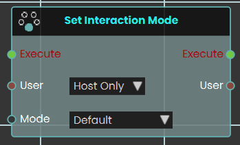
The Set Interaction Mode node dynamically changes how participants engage with the VR environment. When activated, the node evaluates the targeted User input—which can be configured for either "Host Only" or "All Users" and immediately switches their current control state to the selected Mode. The available interaction modes include:
-
Default: The standard, baseline interaction and movement mechanics of the VR Viewer.
-
Drawing: Enables the user to freely draw directly onto 3D surfaces within the scene.
-
Scene Building: Unlocks spatial editing capabilities, allowing the user to dynamically adjust the location, rotation, and scale of 3D objects to freely move and place models around the environment.
-
Measurement: Enables the user to draw straight lines across the scene, accurately measuring distances and lengths in meters.
 Set Night Mode
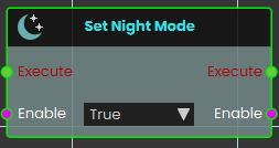
The Set Night Mode node instantly alter the environmental lighting and skybox of the VR scene to nighttime. Once activated, the node evaluates the boolean Enable input—transitioning the scene's overall environment to a dark night mode.
Set Fly Mode
Turns fly mode on or off for a user, letting them move freely up and down through the air instead of being kept on the ground.
What it does
With fly mode on, the chosen user can move up, down, and through the scene freely — handy for inspecting a tall machine from above or getting a bird’s-eye view of a training area. With it off, the user is returned to normal ground-level movement and walks along surfaces as usual.
You pick who this applies to with the User port (just the host, or everyone), and you set whether fly mode is on or off with the Enable port. The node only changes how that user moves — it doesn’t move or alter anything in the scene itself. The same user is passed back out so you can connect more user nodes after it.
Inputs
| Port | Type | What to connect |
|---|---|---|
| Execute | Trigger | Wire this from the previous node’s Execute output to run the node. |
| User | User | Chooses who fly mode applies to. Pick Host Only to affect just the host, or All Users to affect everyone in the session. |
| Enable | True / false | Set to true to turn fly mode on, or false to turn it off and return to normal ground movement. |
Outputs
| Port | Type | What you get |
|---|---|---|
| Execute | Trigger | Fires once the node has finished, so you can continue to the next step. |
| User | User | Passes the same user along so you can chain more user nodes after this one. |
| Enable | True / false | Passes along the on/off value you set, in case a later node needs it. |
Example
| User input | Host Only |
| Enable input | true |
| Enable output | true — the host can now fly freely through the scene |
Tips
- Pair two of these nodes — one with Enable set to
trueand one set tofalse— to let an author toggle flying on and off with a button or voice command. - Remember to turn fly mode back off when it’s no longer needed, so users return to normal walking.
Set Speed Mode
Sets how fast a participant moves around the VR scene — walking, jogging, or running.
What it does
This node changes a participant’s movement speed in the VR environment. When it runs, it looks at the user you target and switches their walking pace to the speed you pick: Walk, Jog, or Run.
You choose whether to change just the host or everyone in the session. The new speed stays in effect until something changes it again, so you can use this node to slow people down in a tight space or let them cover ground quickly in a large scene.
Inputs
| Port | Type | What to connect |
|---|---|---|
| Execute | Trigger | Wire this from the previous node’s Execute output. |
| User | User | Chooses who this applies to. Pick Host Only to change just the host, or All Users to change the speed for everyone in the session. |
| Mode | Choice | The movement speed to apply. Pick one of Walk, Jog, or Run. |
Outputs
| Port | Type | What you get |
|---|---|---|
| Execute | Trigger | Fires once the speed has been set, so you can continue to the next node. |
| User | User | Passes along the same user you targeted, so you can chain more user nodes after this one. |
Example
| User input | All Users |
| Mode input | Run |
| User output | The same participants, ready for the next node |
Tips
- Pair this with a trigger such as entering a large open area to let participants
Run, then switch back toWalkwhen they reach a detailed space. - Use Host Only when you want a guide to keep up with a group without changing everyone’s pace.
Set Speeds Multiplier
Changes how fast a participant moves around in the scene by applying a speed multiplier to them.
What it does
This node sets a movement-speed multiplier on the chosen participant. A value of 1 is normal speed, 2 makes them move twice as fast, and 0.5 slows them to half speed. Use it to speed people up across a large area or slow them down for a careful, detailed task.
The change applies to whichever participant you point the node at — just the host, or everyone. It only adjusts their movement speed; nothing else about the scene or the participant is affected, and the same participant is passed straight out again so you can connect more actions after it.
Inputs
| Port | Type | What to connect |
|---|---|---|
| Execute | Trigger | Wire this from the previous node’s Execute output. |
| User | User | Choose which participant to affect: Host Only or All Users. |
| Value | Number | The speed multiplier. 1 is normal speed, higher is faster, lower is slower. Must not be negative. |
Outputs
| Port | Type | What you get |
|---|---|---|
| Execute | Trigger | Fires once the node has finished. |
| User | User | The same participant you chose, passed along so you can chain more user actions after this one. |
| Value | Number | The multiplier you set, passed along for reuse. |
Example
| User input | All Users |
| Value input | 1.5 |
| Value output | 1.5 |
Tips
- Set the value back to
1when you want participants to return to their normal speed. - A value of
0stops movement entirely — useful for briefly holding everyone in place.
User Name & ID
 Get User ID

The Get User ID node is used to retrieve the unique identifier of the user interacting within the VR environment. This ID can be utilized for various purposes, such as tracking user actions or customizing experiences based on the user.
Example

In this example, the Get User ID node is used to create a student attendance system. When the user triggers the Activate event, the "Get User ID" retrieves the Student ID number and stores it in the "attendance_ID" variable using the "Set Number Variable" node.
Note: To retrieve the User ID, the experience must be run from a logged-in account in SimLab VR Viewer.
 Get User Name

The Get User Name node is used to retrieve the name of the user interacting within the VR environment. This name can be utilized for various purposes, such as personalizing interactions or saving progress tied to a specific user.
Example

In this example, the "Get User Name" node is used to create a student attendance system. When the user triggers the Activate event, the "Get User Name" retrieves the student's name and stores it in the attendance_UserName variable using the "Set String Variable" node.
Note: To retrieve the User Name, the experience must be run from a logged-in account in SimLab VR Viewer.
Material
A material decides how a surface looks in your scene — its color, how see-through it is, and the image (called a texture) painted across it. The nodes on this page let your scene read and change those looks while it is running: fade an object out, recolor a warning light, combine two images, or save a texture to a picture file. You normally get a material by reading it from an object in your scene, then wire it into the Material input of these nodes. Because objects can share the same material, changing a material updates every object using it at once.
What's on this page
- Alpha — read or change how see-through a material is.
- Color — read or change a material’s color.
- Texture — blend two images into a new one, or save a material’s texture out as a picture file.
Alpha
A material’s alpha is how see-through it is, given as a number from 0 (fully transparent) to 1 (fully solid). A value like 0.5 is half see-through. These two nodes read a material’s current alpha or set a new one — useful for fading objects in and out.
Get Material Alpha
Reads how transparent a material is, so you can check its current see-through level.
What it does
This node looks at a material and tells you its alpha — the amount the material lets you see through it. The alpha is given as a Number from 0 (fully see-through) to 1 (fully solid), where a value like 0.5 is half see-through.
It only reads the value — it does not change the material in any way. The same material you fed in comes straight back out, so you can keep working with it in the next node.
Inputs
| Port | Type | What to connect |
|---|---|---|
| Execute | Trigger | Wire this from the previous node’s Execute output. |
| Material | Material | The material you want to check. Connect a node that gives you a material, such as one that reads the material from an object in your scene. |
Outputs
| Port | Type | What you get |
|---|---|---|
| Execute | Trigger | Fires once the node has finished. Wire it to whatever should happen next. |
| Material | Material | The same material you connected, passed straight through unchanged so you can use it again. |
| Value | Number | The material’s alpha, from 0 (fully see-through) to 1 (fully solid). |
Example
| Material input | The glass panel material from your scene |
| Value output | 0.5 |
Tips
- A value of
0means the material is completely see-through, and1means it is fully solid. - Pair this with Set Material Alpha when you want to remember a material’s current transparency, change it for a while, and then put it back.
Set Material Alpha
Changes how see-through a material is, from fully invisible to fully solid.
What it does
This node sets the transparency of a material. You give it a material and a number between 0 and 1: 0 makes the material completely invisible (see-through), 1 makes it completely solid, and values in between make it partly see-through — for example 0.5 is half-transparent.
The change takes effect right away on the material you pass in. The node hands the same material straight back out, along with the transparency value you set, so you can keep using them in the next steps of your script.
Inputs
| Port | Type | What to connect |
|---|---|---|
| Execute | Trigger | Wire this from the previous node’s Execute output. |
| Material | Material | The material whose transparency you want to change. |
| Value | Number | How see-through to make it, from 0 (fully invisible) to 1 (fully solid). Must be in the range 0 to 1. |
Outputs
| Port | Type | What you get |
|---|---|---|
| Execute | Trigger | Fires once the node has finished. |
| Material | Material | The same material you passed in, now with its new transparency. |
| Value | Number | The transparency value you set, passed back so you can reuse it. |
Example
| Material input | The glass material on a window |
| Value input | 0.3 |
| Material output | The same glass material, now mostly see-through |
| Value output | 0.3 |
Tips
- Keep the value between
0and1. Think of it as a percentage:0is 0% solid (invisible),1is 100% solid, and0.5is halfway. - To fade something out over time, run this node repeatedly with a value that steps down from
1toward0.
Color
These two nodes read or change a material’s color. A color is shown as a small swatch you can click to open a color picker — a color wheel with RGB, HSV, and HEX entry. Remember that setting a color changes every object that shares the material.
Get Material Color
Reads the current color of a material so you can use it elsewhere in your scene.
What it does
Give this node a material and it hands you back that material’s current color — the color a viewer sees on every object using that material. The color comes out as a color value (shown as a small colored swatch), which you can feed into other nodes, compare against another color, or store for later.
Reading the color does not change anything — the material keeps looking exactly as it did. If you actually want to change a material’s color, use the Set Material Color node instead, where you pick the new color from a swatch and color picker.
Inputs
| Port | Type | What to connect |
|---|---|---|
| Execute | Trigger | Wire this from the previous node’s Execute output. |
| Material | Material | The material whose color you want to read. Connect a material coming from another node, such as one you picked from an object in your scene. |
Outputs
| Port | Type | What you get |
|---|---|---|
| Execute | Trigger | Fires once the node has finished. |
| Material | Material | The same material you connected, passed straight through — handy for wiring it into the next node without fetching it again. |
| Value | Color | The material’s current color, as a color value you can reuse. It shows as a colored swatch and can be passed to any node that accepts a color. |
Example
| Material input | The material on a warning light in your scene |
| Material output | The same material, passed through |
| Value output | A red color value — for example #C81E1E |
Tips
- Use the Material output to keep your wiring tidy — you can read the color and pass the same material along to the next step in one go.
- Pair this with Set Material Color to save a material’s original color, change it for a while, then put the saved color back later.
Set Material Color
Changes the color of a material so everything using that material takes on the new look.
What it does
This node paints a material with the color you choose. Once it runs, every object in your scene that uses that material is shown in the new color right away — handy for things like turning a warning light red, swapping a wall’s paint, or highlighting a part during a training step.
It only changes the color of the material; the material’s shape, texture, and everything else stay the same. The same material comes back out so you can keep working with it, along with the color you applied.
Inputs
| Port | Type | What to connect |
|---|---|---|
| Execute | Trigger | Wire this from the previous node’s Execute output. |
| Material | Material | The material you want to recolor. Connect it from a node that gives you a material, such as one that picks an object’s material. |
| Color | Color | The new color you want the material to have. Click the color swatch on the node to open the color picker, then pick a color from the wheel, type in RGB or HSV numbers, or enter a HEX code such as #C81E1E. You can also connect a color coming from another node. |
Outputs
| Port | Type | What you get |
|---|---|---|
| Execute | Trigger | Fires once the node has finished, so you can continue to the next step. |
| Material | Material | The same material you sent in, now showing the new color. Pass it on if you want to make more changes to it. |
| Value | Color | The color that was applied, in case you want to reuse it elsewhere. |
Example
| Material input | The material on a warning lamp in your scene |
| Color input | #C81E1E (a red, chosen from the color picker) |
| Material output | The same lamp material, now red |
| Value output | #C81E1E |
Tips
- Because the color is set on the material, every object that shares that material changes together. If you only want one object to change, give it its own material first.
- To put the original color back later, save it first with a Get Material Color node, then feed that saved color back into this node when you want to restore it.
Texture
A texture is the image painted across a material’s surface. These two nodes work with image files inside your project: one blends two images into a new one, the other saves a material’s texture out as a PNG picture. Both do their work in the background and hand back a true/false result telling you whether they succeeded.
Blend Textures
Combines two image files from your project into a single new image, with one laid on top of the other.
What it does
This node takes two images that already live in your project — a Base image and an Overlay image — and lays the Overlay on top of the Base to create one combined picture. It saves the result as a brand-new image file inside your project and gives you back that new file’s name, so you can use it as a texture, a label, or any other image.
Your two original images are left untouched — the node only creates a new combined image and never changes the Base or the Overlay. Because building the new image can take a moment, this node works in the background: its Execute output fires only once the blend has finished. You also get a true/false result telling you whether it worked.
Inputs
| Port | Type | What to connect |
|---|---|---|
| Execute | Trigger | Wire this from the previous node’s Execute output. |
| Base | Text | The name of the bottom image — the one that goes underneath. Use a short file name (including its extension) for an image inside your project, such as wood_panel.png. |
| Overlay | Text | The name of the top image — the one laid over the Base. Use a short file name (including its extension) for an image inside your project, such as logo.png. |
Outputs
| Port | Type | What you get |
|---|---|---|
| Execute | Trigger | Fires once the two images have finished blending. Wire this to whatever should happen next. |
| Base | Text | The Base image name you provided, passed straight through so you can reuse it. |
| Overlay | Text | The Overlay image name you provided, passed straight through so you can reuse it. |
| Success | True / false | true if the new combined image was created, or false if it could not be made (for example, if one of the image names was wrong). |
| FileName | Text | The short file name of the new combined image inside your project. When the blend fails this comes back empty. |
Example
| Base input | wood_panel.png |
| Overlay input | logo.png |
| Success output | true |
| FileName output | wood_panel_blended.png |
Tips
- Make sure both images are already part of your project and that you type their names exactly, including the file extension (for example
.png). - Check the Success output before using the new image — if it comes back
false, the FileName will be empty. - The order matters: the Overlay always sits on top of the Base. Swap the two inputs if the result looks upside-down.
Save Texture
Saves a material’s texture image out as a PNG picture file inside your project.
What it does
This node takes the texture (the surface image) used by a material and writes it out as a PNG picture file inside your current SimLab project. You give it the material to read from and a file name to save under, and it produces that picture for you.
It does not change the material or its texture in any way — it simply makes a copy of the texture as a separate picture file. The node works in the background, so its Execute output only fires once the picture has been fully saved. You also get a true/false result telling you whether the save worked.
Inputs
| Port | Type | What to connect |
|---|---|---|
| Execute | Trigger | Wire this from the previous node’s Execute output. |
| Material | Material | The material whose texture you want to save. Its surface image is the one that gets written out as a PNG. |
| FileName | Text | The name to save the picture under, including the .png ending — for example crate_diffuse.png. This is a short name; the file is saved inside your current project. |
Outputs
| Port | Type | What you get |
|---|---|---|
| Execute | Trigger | Fires once the picture has finished saving. Wire this to whatever should happen next. |
| Material | Material | The same material you passed in, handed straight back so you can keep using it in later nodes. |
| FileName | Text | The short name the picture was saved under, such as crate_diffuse.png. |
| Success | True / false | true if the picture was saved, or false if it could not be saved (for example, the material has no texture). |
Example
| Material input | The material on a crate object |
| FileName input | crate_diffuse.png |
| FileName output | crate_diffuse.png |
| Success output | true |
Tips
- Remember to include the
.pngending in the file name yourself — for examplecrate_diffuse.png. - Check the Success output before relying on the saved picture; a material with no texture image will return
false. - Because the save happens in the background, build the rest of your steps off this node’s Execute output so they only run after the picture is ready.
 Copy Material
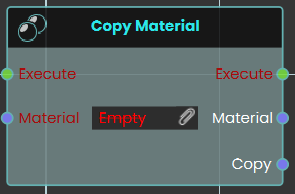
The Copy Material node duplicates an existing material and create a completely independent instance. Upon triggering the Execute input, the node takes the specified Material input and outputs a newly generated Copy of that material, which can then be freely modified without altering the original source.
 Copy Material Properties
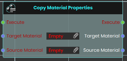
The Copy Material Properties node transfers visual attributes directly from one material to another without generating a new instance. When the Execute input is triggered, the node takes the characteristics of the Source Material input and applies them directly to the Target Material input, instantly overwriting the target's previous properties.
Example:
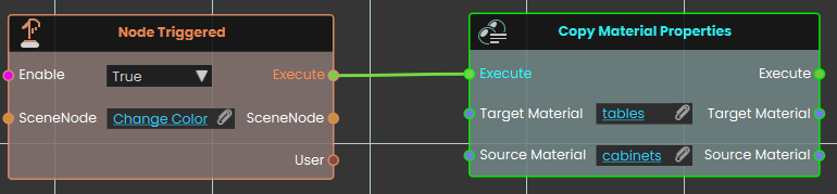
In this example, triggering the "Change Color" object prompts the system to execute the Copy Material Properties node. Once activated, the node takes all the visual attributes from the "cabinets" source material and immediately applies them to the "tables" target material, causing any 3D objects using the tables material to instantly match the appearance of the cabinets.
Material \ Texture
 Set Texture From File
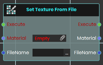
This node replaces the current texture of a specified material with a 2D image file stored in your Resource Management system. By inputting the exact file name, you can dynamically update the visual appearance of any object using that material during the experience.
Execution
 Branch on Expression
 The Branch on Expression response enables the user to evaluate an expression with the possible outputs of True or False each time the event connected to it is triggered. Once the response is executed, the result of the evaluation can be acquired through the True or False ports.
Example

In this example, a Branch on Expression response is used to evaluate an expression once the user triggers the object named Activate. The result of the expression, which will be either True or False, if the result was true, the object named "Variable_01" will be shown, if it was false, the object named "Variable_02" will be shown.
 Delay
Delay

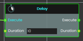
The Delay node waits for the specified Duration (in seconds), then executes the node linked to its Execute output.
Duration can be an integer or a float less than one to achieve sub-second delays.
 Loop
Loop

The Loop node enables the user to repeatedly execute a connected response for a specified number of times as defined in the Number of Loops field. Each time the event connected to the loop is triggered, the response is executed repeatedly, and the loop continues until the assigned number of repetitions is completed.
Example

In this example, a Loop node is used to repeatedly execute the connected response that decreases the value of a number variable by one. The Decrement response is repeated for the number of times specified in the Number of Loops field, with the duration between each repetition set in the Interval field. Once the assigned number of repetitions is completed, the sound named Countdown_Over plays.
 Run Script

The Run Script node allows the user to execute advanced functions using the Lua programming language. This node provides flexibility by enabling custom scripts to be triggered when an event occurs. Allowing for complex operations and logic to be carried out as defined in the script. This node is ideal for scenarios requiring functionality beyond the standard nodes, offering advanced customization and control over the system.
You can read about Lua Scripting in SimLab Training builder through the following Blog:
 Trigger Custom Event

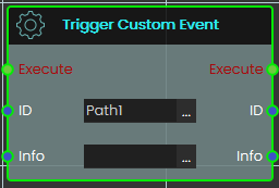
Calling this Trigger Custom Action will execute the corresponding Custom Action event (based on the matching ID), passing along any optional information provided in the info field.
This is useful when you want multiple paths in your experience to produce the same response — without duplicating it each time.
Branch
Sends the action down one of two paths depending on whether a yes/no value is true or false.
What it does
Branch is a fork in the road for your scene’s actions. When it runs, it looks at the yes/no value wired into Condition. If that value is true, it fires the True path; if it’s false, it fires the False path.
Exactly one of the two paths fires every time — never both, and never neither. This lets you say “if this is the case, do these steps; otherwise, do those steps instead.” Branch only chooses a direction; it doesn’t change the value you give it.
Inputs
| Port | Type | What to connect |
|---|---|---|
| Execute | Trigger | Wire this from the previous node’s Execute output. |
| Condition | True / false | The yes/no value to test. Wire in anything that gives a true/false result — for example a check on whether a door is open or whether a score has passed a target. |
Outputs
| Port | Type | What you get |
|---|---|---|
| True | Trigger | Fires when the Condition is true. Wire the steps you want to run in that case here. |
| False | Trigger | Fires when the Condition is false. Wire the steps you want to run in that case here. |
Example
| Condition input | true |
| True output | Fires — the steps wired here run (for example, play a success sound). |
| False output | Does not fire this run. |
Tips
- Leave the False path empty if you only care about acting when the Condition is true — nothing happens on that side and the rest of your scene carries on.
- To choose between more than two paths, chain several Branch nodes together, sending the False path of one into the next.
Do Then
Splits one trigger into two that fire in a guaranteed order — first the “Execute” output, then the “Then” output, right after.
What it does
When this node runs, it fires its “Execute” output first and then immediately fires its “Then” output. Use it when you want two things kicked off from a single trigger and you care which one starts first.
The node only controls the order the two outputs fire in — it does not wait for the work wired to “Execute” to finish before firing “Then.” The “Then” output always fires, no matter what happens on the “Execute” side. This node doesn’t change or hold onto any of your scene data; it simply directs the flow.
Inputs
| Port | Type | What to connect |
|---|---|---|
| Execute | Trigger | Wire this from the previous node’s Execute output to run this node. |
Outputs
| Port | Type | What you get |
|---|---|---|
| Execute | Trigger | Fires first. Wire this to the steps you want to start before the “Then” steps. |
| Then | Trigger | Fires right after “Execute,” without waiting for the “Execute” steps to finish. It always fires. Wire this to the steps you want to start second. |
Example
| Execute input | Triggered when a button in the scene is clicked |
| Execute output | Fires first — starts playing a door-opening animation |
| Then output | Fires right after — shows a hint label to the user |
Tips
- Reach for this when two actions share one trigger and you want a reliable order — the “Execute” output’s steps always start before the “Then” output’s.
- Remember that “Then” does not wait for the “Execute” side to finish. If you need the second action to begin only after the first one has fully completed, drive it from the end of the first chain instead.
SceneNode \ Management
 Cast SceneNode

The Cast SceneNode enables the user to change the type of a SceneNode by selecting a typeInfo from the list, such as sound, 3D object, video, gadget, or camera. This node identifies the assigned SceneNode as the chosen type, allowing it to function accordingly within the VR environment.
Example

In this example, Animals sounds are assigned to the animals as SceneNode type

A Cast SceneNode is used to identify the SceneNode of an animal object (dog, cat, and horse) as a sound. An attribute named "Sound" is added to all three animals, and the corresponding sound is assigned to each. When the user triggers the animal SceneNode, the Cast SceneNode plays the sound assigned in the attribute.
 Set Node Collision Enabled
The Set Node Collision Enabled node is used to enable or disable collision for the user. This can be utilized to allow the user to pass through objects or be blocked by them within the VR environment.
Example
In this example, the Set Node Collision Enabled node is used to disable collision for the user when the scene starts. The wall is assigned as the target object, and the collision is set to "False," allowing the user to pass through it.
This is shown in the following tutorial
Delete SceneNode
The Delete SceneNode node enables users to remove a specified object from the scene during a VR Experience. This node allows for dynamic scene modifications by deleting objects based on interactions or conditions, making the environment more interactive and adaptable. Once executed, the specified object is permanently removed from the scene.
Example
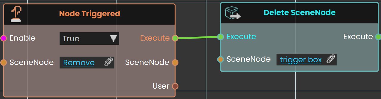
In this example, the Delete SceneNode node is used to remove a trigger box from the scene. The Node Triggered event is activated when the user triggers or clicks on an object named "Remove." As soon as the object is triggered, the Delete SceneNode node removes the trigger box from the scene, preventing further interactions with it.
 Enable Walk-Through
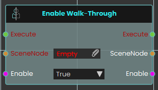
The Enable Walk-Through node explicitly controls the physical collision properties of a targeted 3D object within the VR Viewer. When activated, the node uses the boolean Enable input to determine the collision state of the specified SceneNode—allowing users to seamlessly pass directly through the object without physical obstruction if set to True.
 Find Node By Name
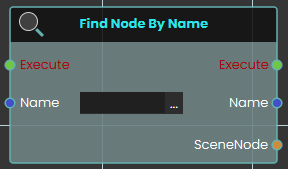
The Find Node By Name node searches the VR environment and dynamically locate a specific 3D object based on its assigned text identifier. When activated, the node takes the exact string provided in the Name input, searches the scene to find the corresponding object, and outputs that specific SceneNode reference.
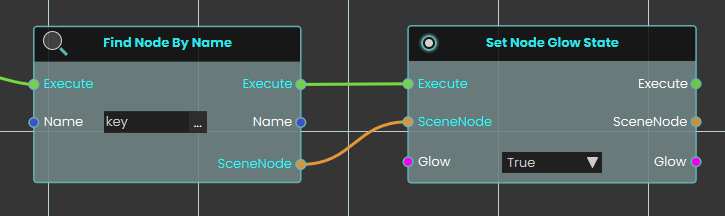
 Get Node Name
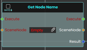
The Get Node Name node retrieves the exact text identifier of a specific 3D object within the scene. When activated, the node takes the targeted SceneNode input, extracts its assigned name, and outputs this text as a string value through the Result pin.
 Make Node Copy
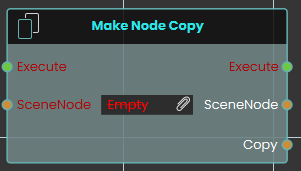
The Make Node Copy node duplicates a specific 3D object along with an independent copy of its material. Once activated, the node takes the targeted SceneNode input and generates a completely separate Copy, ensuring that any subsequent material or texture changes applied to this new object do not affect the original source.
 Make Node Instance
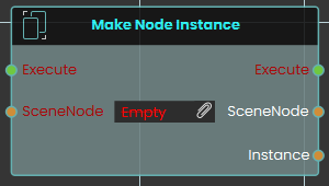
The Make Node Instance node generates a direct clone of a specific 3D object in the scene. When activated, the node takes the targeted SceneNode input and creates a new Instance that shares the exact same material properties as the original.
Example:
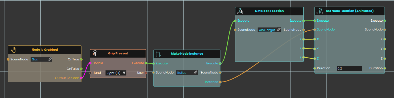
In this example, we create a simple shooting mechanic where firing a gun generates and shoots a bullet toward a target:
-
A Node Is Grabbed node continuously checks if the user is holding the "Gun" object, enabling the next node if the condition is met.
-
A Grip Pressed event node listens for the user to press the right hand's grip button, acting as the trigger to fire the weapon.
-
Once the grip is pressed, the Make Node Instance node activates, immediately generating a new instance of the "Bullet" object in the scene.
-
A Get Node Location node is then used to retrieve the exact X, Y, and Z coordinates of a specific "AimTarget" object.
-
Finally, a Set Node Location (Animated) node takes the newly generated bullet instance and smoothly moves it to the AimTarget's coordinates over a quick duration of 0.2 seconds, simulating a flying projectile.
 Set Node Simulate Physics
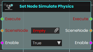
The Set Node Simulate Physics node activates or deactivates real-time physics calculations for a specific 3D object within the VR Viewer. When activated, the node uses the boolean Enable input to determine the object's physical state, allowing the object to react to gravity, collisions, and user interactions based on its assigned material physics properties
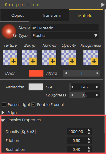
To configure how an object behaves during simulation, navigate to the Properties panel and select the Material tab. Under the Physics Properties section, you can adjust specific physical attributes for that material, such as its Density, Friction, and Restitution, which directly impact how the object interacts with the environment when physics are enabled.
Is Same Node
Checks whether two scene nodes are the same node, and gives you a true/false answer.
What it does
You hand this node two scene nodes — SceneNode A and SceneNode B — and it tells you whether they are the same. The answer comes out of the Result port as true or false: true when the two are the same, false when they are different.
This node only looks — it never changes either scene node. Both scene nodes also come straight back out unchanged, so you can keep wiring from them to whatever should happen next.
Inputs
| Port | Type | What to connect |
|---|---|---|
| Execute | Trigger | Wire this from the previous node’s Execute output. |
| SceneNode A | Scene node | The first scene node you want to compare. |
| SceneNode B | Scene node | The second scene node you want to compare against the first. |
Outputs
| Port | Type | What you get |
|---|---|---|
| Execute | Trigger | Fires once the node has finished. |
| SceneNode A | Scene node | The same first scene node you connected, passed straight back out unchanged so you can keep wiring from it. |
| SceneNode B | Scene node | The same second scene node you connected, passed straight back out unchanged so you can keep wiring from it. |
| Result | True / false | True when the two scene nodes are the same, false when they are different. |
Example
| SceneNode A input | The Front Door node picked earlier in your script |
| SceneNode B input | The node the user just clicked |
| Result output | true if the clicked node is the Front Door, otherwise false |
Tips
- Wire the Result into a node that branches on true/false to do one thing when the two match and another when they don’t — for example, only open a door when the clicked node really is that door.
Set Socket Node Enabled
Turns a snapping socket on or off, so you can control whether objects are allowed to snap into that spot.
What it does
A socket is a spot in your scene that objects can snap into — for example the place where a bolt seats into a housing, or where a tool clips onto a wall mount. This node lets you switch one of those sockets on or off while the scene is running. When you set it to on, objects can snap into the socket as usual; when you set it to off, the socket stops accepting anything, so nothing can snap there until you turn it back on.
This is handy for guiding a trainee through steps in order — you can keep a socket switched off until it is the right time to use it, then switch it on so the next part can be placed. The node only changes whether that socket is active; it does not move, snap, or remove anything already in the scene. It hands the same object and the same on/off value back out so you can keep wiring from them.
Inputs
| Port | Type | What to connect |
|---|---|---|
| Execute | Trigger | Wire this from the previous node’s Execute output to run the node at the moment you want the socket switched. |
| SceneNode | Scene node | The socket you want to switch — the snapping spot in your scene whose state you want to change, such as a BoltSocket_01. |
| Enable | True / false | Whether the socket should be on or off. Connect true to switch it on so objects can snap into it, or false to switch it off so nothing can snap there. |
Outputs
| Port | Type | What you get |
|---|---|---|
| Execute | Trigger | Fires once the node has finished, so you can continue to the next step. |
| SceneNode | Scene node | The same socket you put in, passed straight back out so you can keep wiring from it without looking it up again. |
| Enable | True / false | The same on/off value you put in, passed back out in case you want to reuse it further along. |
Example
| SceneNode input | BoltSocket_01 |
| Enable input | true — switch the socket on so the bolt is now allowed to snap into it |
| SceneNode output | BoltSocket_01, handed straight back so you can wire it into the next node |
Tips
- Keep a socket switched off until it is the right step, then switch it on — a good way to make sure parts are placed in the order you intend.
- Switching a socket off does not remove anything already snapped into it; it only stops new objects from snapping there.
SceneNode \ Transform
 Get Node Transform
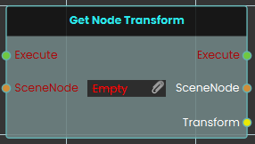
The Get Node Transform node retrieves the complete spatial data—including the exact location, rotation, and scale values—of a specific 3D object in the scene. When activated, the node takes the targeted SceneNode input, extracts its current transform matrix, and outputs this combined information through the Transform pin.
Set Node Transform
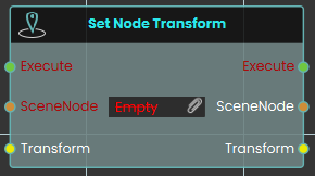
The Set Node Transform node instantly applies a complete set of spatial data—encompassing location, rotation, and scale—to a specific 3D object. Once activated, the node evaluates the targeted SceneNode and immediately updates its physical presence in the scene to perfectly match the data provided through the Transform input.
 Set Node Transform (Animated)
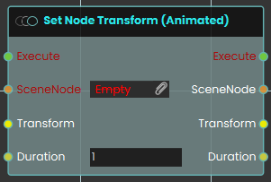
The Set Node Transform (Animated) node functions similarly to the standard set transform node, but it smoothly transitions the 3D object to the new location, rotation, and scale over a defined period. When activated, the node takes the targeted SceneNode and seamlessly tweens its spatial data to match the provided Transform input over the specific amount of time defined by the numerical Duration input (measured in seconds).
 Swap Nodes Transform
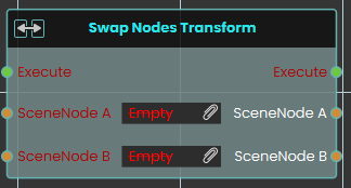
The Swap Nodes Transform node instantly exchanges the complete spatial data—including location, rotation, and scale—between two distinct 3D objects in the scene. When activated, the node evaluates the targeted objects provided in the SceneNode A and SceneNode B inputs and simultaneously swaps their placements, rotations, and proportions.
Transform Node to Node (Animated)
Smoothly moves one or more objects so they end up exactly where a second object is — same position, rotation, and size — over a set number of seconds.
What it does
This node takes a target object and reads its full placement in the scene — its position, its rotation, and its size. It then animates your chosen object(s) so that, over the time you set, they smoothly travel to that same placement and come to rest matching the target exactly.
The movement is measured in absolute scene coordinates, so your object lands at the target’s real position in the scene regardless of any groups either one belongs to. The target object itself is never changed — it stays put, and only the object(s) you pointed at the SceneNode input move. The non-animated version of this node snaps the object into place instantly; this version eases it there over the Duration you choose.
Inputs
| Port | Type | What to connect |
|---|---|---|
| Execute | Trigger | Wire this from the previous node’s Execute output to start the movement. |
| SceneNode | Scene node | The object (or objects) you want to move. Each one will travel to match the target. |
| ToNode | Scene node | The target object whose place you want to match. This object is read only — it doesn’t move. |
| Duration | Number | How many seconds the smooth movement should take. Leave it at 2 for a gentle two-second glide, or set a smaller number to make it faster. |
Outputs
| Port | Type | What you get |
|---|---|---|
| Execute | Trigger | Fires once the node has finished. |
| SceneNode | Scene node | The same object(s) you moved, passed straight through so you can connect more nodes after this one. |
| ToNode | Scene node | The same target object, passed through unchanged. |
| Duration | Number | The same number of seconds you set, passed through so you can reuse it. |
Example
| SceneNode input | The Drone object |
| ToNode input | The Landing Pad object |
| Duration input | 3 (the drone glides onto the landing pad over three seconds) |
| SceneNode output | The Drone, now resting in the landing pad’s place — ready to chain into the next node |
Tips
- Because the object matches the target’s rotation and size as well as its position, you can use an empty or hidden helper object as a “marker” to define exactly how and where something should arrive.
- Set Duration to
0for an instant jump, or use the non-animated version of this node if you never want the smooth motion.
SceneNode \ Transform \ Location
 Get Node Visual Location

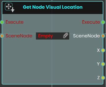
The Get Node Visual Location node enables the system to retrieve the exact X, Y, and Z coordinates of a SceneNode based on its absolute visual representation in the 3D scene.
Unlike standard location nodes that calculate position relative to a parent object, this node fetches the true visual position of the object within the environment, completely unaffected by the scene's parent-child hierarchy system.
Set Node Visual Location
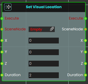
The Set Node Visual Location node enables the system to instantly move a SceneNode to specific X, Y, and Z coordinates within the absolute visual space of the 3D scene. By directly altering where the object appears visually, this node completely bypasses any positional offsets or transformations that the object might normally inherit from its parent hierarchy.
Example
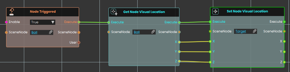
In this example, an interaction is set up to match the positions of two independent objects.
-
Upon interacting with the "Ball" object, the Node Triggered event initiates the execution flow.
-
The Get Node Visual Location node extracts the true visual X, Y, and Z coordinates of the "Ball" in the scene.
-
These coordinate values are then fed directly into the X, Y, and Z inputs of a Set Node Visual Location node assigned to a "Target" object. This instantly moves the Target to the exact visual location of the Ball, regardless of how deeply nested either object is within the scene's hierarchy.
Set Node Visual Location (Animated)
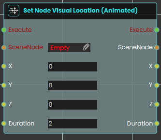
The Set Node Visual Location (Animated) node enables the system to smoothly move a SceneNode to specific X, Y, and Z coordinates within the absolute visual space of the 3D scene over a set period.
Similar to the standard Set Node Visual Location node, this movement completely bypasses any positional offsets or transformations inherited from the object's parent hierarchy. However, this animated variant includes an additional Duration parameter. Instead of instantly snapping the object to the new coordinates, this node creates a smooth transition (tweening) from its current visual location to the target location over the specified number of seconds.
 Fall To Surface
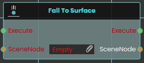
The Fall To Surface node instantly repositions a specific 3D object directly onto the nearest 3D surface located immediately below it in the scene. When activated, the node takes the targeted SceneNode input and immediately updates its vertical placement to simulate a sudden, instantaneous drop, resting the object perfectly against the underlying geometry.
Fall To Surface (Animated)
The Fall To Surface (Animated) node functions similarly to the standard fall node, but instead of an instant drop, it smoothly transitions the 3D object down to the nearest underlying surface over a defined period. Once activated, the node takes the targeted SceneNode and seamlessly tweens its vertical descent until it rests on the geometry below, completing the fall animation over the exact amount of time specified by the numerical Duration input (measured in seconds).
 Get Node Location

The Get Node Location response obtains the X, Y, and Z coordinates of an object's location each time the event connected to it is triggered. Once the response is executed, the coordinates can be acquired through the X, Y, and Z ports.
Example

In this example, a Get Node Location response is used to obtain the X, Y, and Z coordinates of an object named Table once the user triggers the object named Activate. The coordinates are then stored in variables named X, Y, and Z, which can be connected to a variable writer to be displayed during the VR Experience.
 Set Node Location

The Set Node Location response enables the user to set the location of an object to specific X, Y, and Z coordinates by either typing in the numerical values or by attaching a variable node to those ports. Once the response is executed, the object's new location is applied using the provided coordinates.
Example

In this example, a Set Node Location response is used to assign the X, Y, and Z coordinates stored in variables named X, Y, and Z to an object named Pot once the user triggers the object named Activate. The object's new location is set based on these coordinates, allowing the updated position to be reflected during the VR Experience.
Set Node Location (Animated)
The Set Node Location (Animated) node enables the system to smoothly move a SceneNode to a specific global coordinate in the 3D space over a set period. this node creates a seamless tweening effect from the object's current position to its new target destination
This differs significantly from the standard Set Node Location node, which instantly snaps or teleports the object to the new coordinates without any transition. The animated variant is ideal for creating moving platforms, sliding doors, or moving vehicles.
Example
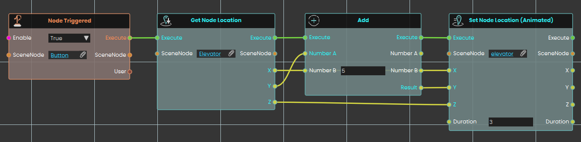
In this example, an interactive elevator mechanism is created.
-
Upon interacting with the button object, the Node Triggered event initiates the execution flow.
-
The Get Node Location node is used to retrieve the current X, Y, and Z global coordinates of the "Elevator" object.
-
To move the elevator up, the Y-axis coordinate is passed into an Add node, where 5 units are added to its current value. The X and Z coordinates remain unchanged.
-
Finally, the Set Node Location (Animated) node applies these new coordinates to the elevator object. The Duration parameter is set to 3, meaning it will take exactly 3 seconds for the elevator to smoothly transition (tween) to its new position 5 units higher.
Local position
These behave like the position nodes above, but the X, Y, and Z values are measured relative to the object’s parent or group instead of the whole scene. If the object isn’t inside a group, the result is the same as the world versions.
Get Node Location (Local)
Reads where an object currently sits, measured relative to its parent or group.
What it does
This node looks at an object in your scene and tells you its position as three numbers — X, Y, and Z — given in meters. The position is local, which means it is measured relative to the object’s parent or group: if that parent or group is moved, turned, or resized, the local position stays the same. (If the object has no parent or group, its local position and its position in the whole scene are the same.)
It only reads the position — it doesn’t move the object or change anything else in your scene. Use it whenever you need to know where something is so you can react to it, compare it, or feed the numbers into another node.
Inputs
| Port | Type | What to connect |
|---|---|---|
| Execute | Trigger | Wire this from the previous node’s Execute output. |
| SceneNode | Scene node | The object whose position you want to read. |
Outputs
| Port | Type | What you get |
|---|---|---|
| Execute | Trigger | Fires once the node has finished. |
| SceneNode | Scene node | The same object passed straight through, so you can chain more nodes onto it. |
| X | Number | The object’s position along the X axis, in meters. |
| Y | Number | The object’s position along the Y axis, in meters. |
| Z | Number | The object’s position along the Z axis, in meters. |
Example
| SceneNode input | A wrench resting on a workbench |
| X output | 1.5 |
| Y output | 0.75 |
| Z output | 2 |
Tips
- If you want the object’s position in the whole scene rather than relative to its parent or group, use the matching node without “(Local)” in its name.
Set Node Location (Local)
This node moves an object to a position you choose, measured relative to its parent or group.
What it does
You give it an object and three numbers — X, Y, and Z, in meters — and it places that object at exactly that position. The position is “local,” meaning it is measured relative to the object’s parent or group: if you later move, turn, or resize that parent or group, this object keeps the same local position and travels along with it. If the object has no parent or group, its local position is the same as its position in the whole scene.
Only the object you connect is moved — no other objects in the scene are affected. The change happens instantly. The node then hands the same object straight back out, along with the X, Y, and Z values you set, so you can connect it to more nodes.
Inputs
| Port | Type | What to connect |
|---|---|---|
| Execute | Trigger | Wire this from the previous node’s Execute output. |
| SceneNode | Scene node | The object you want to move. |
| X | Number | The position along X, in meters. Leave at 0 for no change on this axis. |
| Y | Number | The position along Y, in meters. Leave at 0 for no change on this axis. |
| Z | Number | The position along Z, in meters. Leave at 0 for no change on this axis. |
Outputs
| Port | Type | What you get |
|---|---|---|
| Execute | Trigger | Fires once the node has finished. |
| SceneNode | Scene node | The same object, passed through so you can chain more nodes onto it. |
| X | Number | The X position you set, in meters. |
| Y | Number | The Y position you set, in meters. |
| Z | Number | The Z position you set, in meters. |
Example
| SceneNode input | The crate you want to reposition |
| X input | 1.5 |
| Y input | 0.75 |
| Z input | 2 |
| SceneNode output | The same crate, now at that position, ready to chain |
Tips
- Because the position is local, it is easiest to picture when the object sits inside a group: the numbers are measured from that group, not from the whole scene.
- To move the object using absolute scene coordinates instead, use the matching node without “(Local)” in its name.
Set Node Location (Local, Animated)
Smoothly moves a 3D object to a new spot over a set number of seconds, using a position measured relative to the object’s parent or group.
What it does
This node glides an object from where it is now to a new position you choose, given as X, Y, and Z values in meters. Instead of snapping there instantly, it animates the move over the number of seconds you set in Duration, so the object appears to travel to its new spot.
The position is “local,” meaning it is measured relative to the object’s parent or group rather than the whole scene. If you later move, turn, or resize that parent or group, this local position stays the same. (If the object has no parent or group, its local position is just its position in the scene.) Only the object you connect is affected — nothing else in the scene moves.
Inputs
| Port | Type | What to connect |
|---|---|---|
| Execute | Trigger | Wire this from the previous node’s Execute output to start the movement. |
| SceneNode | Scene node | The 3D object you want to move. You can connect more than one object to move them all the same way. |
| X | Number | The X position to move to, in meters. |
| Y | Number | The Y position to move to, in meters. |
| Z | Number | The Z position to move to, in meters. |
| Duration | Number | How many seconds the smooth movement should take. Must be zero or more; 2 by default. |
Outputs
| Port | Type | What you get |
|---|---|---|
| Execute | Trigger | Fires to let the flow continue once the movement has been applied. |
| SceneNode | Scene node | The same object (or objects) passed straight through, so you can chain more nodes onto it. |
| X | Number | The X position you asked for, passed through. |
| Y | Number | The Y position you asked for, passed through. |
| Z | Number | The Z position you asked for, passed through. |
| Duration | Number | The number of seconds you set, passed through. |
Example
| SceneNode input | A crate object in your scene |
| X input | 1.5 |
| Y input | 0.75 |
| Z input | 2 |
| Duration input | 2 (the crate glides to its new spot over 2 seconds) |
Tips
- For an instant jump with no animation, use the non-animated version of this node instead.
- Set Duration to
0for the fastest possible move. - To move an object to a spot fixed in the whole scene rather than relative to its parent or group, use the world version of this node (the one without “(Local)” in its name).
SceneNode \ Grab
 Ignore grabbing
The Ignore Grabbing node explicitly prevents a specific 3D object from being picked up or interacted with by the user's hands during the VR experience. When activated, the node disables the grabbable state of the targeted SceneNode if set to True. This node is highly useful for complex models where you want to enforce realistic interactions by restricting grip points, allowing you to easily exclude certain parts of a grouped object from being grabbed without having to detach or separate the components from the main assembly.
Example:
In this example, we configure a screwdriver so that the user can only pick it up by its handle, preventing them from grabbing it awkwardly by the metal rod or tip:
If Set Node Grabbable State node is used on the handle part of the screw driver alone, only the handle will move along with the grabbing hand, leaving the rest of the screw driver's assembly in place. Instead, Ignore Grabbing node should be used to exclude unwanted parts from being grabbed:
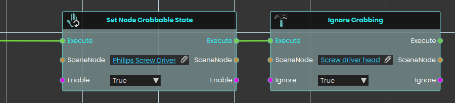
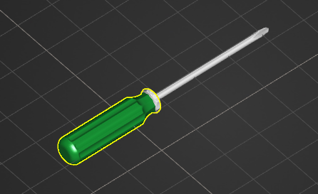
-
A Set Node Grabbable State node is activated to make the entire "Philips Screw Driver" parent group grabbable.
-
The execution flow immediately continues into an Ignore Grabbing node.
-
The specific "Screw driver head" object is assigned to the SceneNode input, and the Ignore boolean is set to True.
-
As a result, the metal tip is excluded from being a valid grab target, forcing the user to grab the tool properly by its handle while still ensuring the entire screwdriver assembly moves together as one cohesive object in the user's hand.
 Set Grabbable Sequence
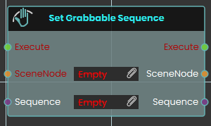
The Set Grabbable Sequence node makes a specific 3D object interactively grabbable by assigning an animation sequence to it during the VR experience. Once activated, the node evaluates the targeted SceneNode and attaches the specified Sequence input, defining exactly how the object animates when grabbed and manipulated by the user. This versatile node can be used to add a sequence, dynamically switch between different sequences on the fly, or completely remove an existing sequence from a grabbable object before continuing the logic flow.
Example:
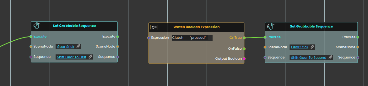
In this example, we use the Set Grabbable Sequence node to create a dynamic gear stick that changes states based on the user's interactions:
-
A Set Grabbable Sequence node is used to make a "Gear Stick" object grabbable and attaching an animation sequence that, when grabbed, shifts the gear to first.
-
A Watch Boolean Expression node continuously monitors a string variable named "Clutch".
-
When the "Clutch" variable is set to "pressed", the watch node passes its OnTrue execution path to a second Set Grabbable Sequence node, which changes the grabbable object's sequence to a "Shift Gear To Second" sequence.
Tip:
Using the Set Grabbable Sequence node without attaching a sequence will disable the grabbing state of an object.
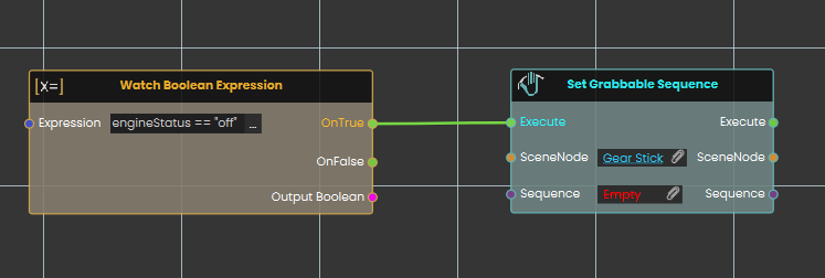
Here, another Watch Boolean Expression node is used to monitor a variable called "engineStatus". When the "engineStatus" variable is set to "off", it triggers a Set Grabbable Sequence node targeting the gear stick, but this time with no sequence attached (Empty). Leaving the sequence input empty completely disables the grabbing interaction, turning the gear stick back into a still, non-interactable object.
 Set Node grabbable State
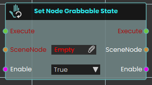
The Set Node Grabbable State node evaluates the boolean Enable input to determine the targeted SceneNode's grabbable status—making the object fully grabbable by the user if set to True, or disabling grab interactions entirely to make it a static object if set to False.
Resource
 Delete Resource
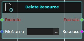
The Delete Resource node enables the system to remove specific resources currently stored in the SimLab File Vault. This node simply requires the exact "FileName" of the target file as an input to execute the deletion. It outputs a "Success" boolean to confirm whether the specified file was successfully removed from the vault.
 Download Resource

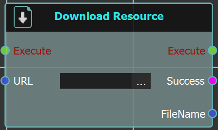
The Download Resource node enables the system to download a specific file directly from the SimLab File Vault while a user is actively engaged inside a VR experience. This node requires the exact URL of the vault file to be linked into the node's input. Upon execution, it retrieves the file and provides a "Success" status alongside the downloaded "FileName" to be used in subsequent logic.
For more information, refer to SimLab Vault tutorial below:
 Get Path From Resource
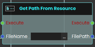
The Get Path From Resource node enables the system to retrieve the exact URL or local file path of a specific resource or file. This node requires the exact "FileName" of the target file as an input.
 Save VRPackage

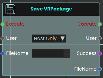
The Save VRPackage node enables the system to save the current, active VR experience as a standalone .vrpackage file, directly from within the VR session itself. It requires a "FileName" to name the new package and includes a "User" dropdown (e.g., "Host Only") to specify which user is authorizing the save. It outputs a "Success" boolean and the final "FileName" to confirm the action.
 Upload Media From User
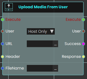
The Upload Media From User node functions similarly to the standard Upload Resource node by sending files to the SimLab File Vault via a designated URL. This node is specifically designed for multiplayer VR Collaboration environments.
It allows an administrator or host to target a specific user (via the "User" dropdown) and upload a file from that user's local device directly to the central File Vault. This is crucial for sharing media when a file exists only on an individual participant's machine and not on the host's device. Like the standard upload node, it outputs a "Success" boolean.
 Upload Resource
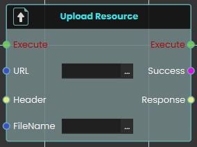
The Upload Resource node enables the system to send and save resources to the SimLab File Vault during a live VR experience. This node requires the destination URL for the file vault, as well as the assigned "FileName" for the file being uploaded and outputs a "Success" boolean.
For more information, refer to SimLab Vault tutorial below:
External Connection \ WebSocket
 Open External Connection
SimLab Composer 14 introduces WebSocket support, enabling seamless integration with external systems allowing it to work with external hardware, co-simulation engines, and websites, unlocking numerous possibilities.
The WebSocket nodes (Open External Connection, Send Message, and On Message Received) are exclusively available in the Ultimate Edition.
The Open External Connection node enables the opening of a WebSocket connection to an external system. When the Auto Handle Lua is set to true, incoming messages containing Lua scripts will be automatically executed. This allows for real-time interaction between SimLab Composer and external systems, such as co-simulation engines or hardware, with the ability to dynamically execute Lua code as part of the interaction.
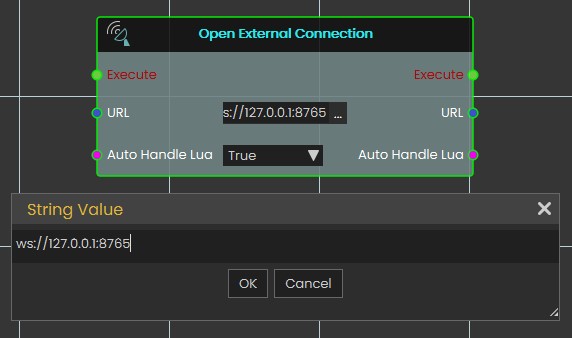
Input Ports:
- Execute
- URL: WebSocket URL that includes the server IP address, port, channel (optional). Example: ws://server1.simlab-soft.com:8765/robots_1
- Auto Handle Lua: Incoming messages containing Lua scripts will automatically execute those scripts If enabled (True).
Output Ports:
- Execute
- URL
- Auto Handle Lua
 Send Message
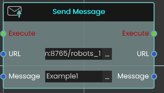
The Send Message node allows you to communicate with the WebSocket server by sending messages. It is essential to ensure that the message format follows the protocol that the server and other clients can process. This node enables real-time interaction with external systems, making it possible to transmit data or commands to connected servers or clients.
Input Ports:
- Executive
- URL: WebSocket URL that includes the server IP address, port, and channel (optional). Example: ws://server1.simlab-soft.com:8765/robots_1
- Message
Output Ports:
- Execute
- URL
- Message
Media
 Message Box \ Show Message Box
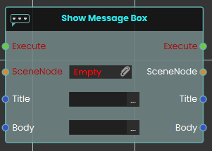
The Show Message Box node displays a floating text panel directly above a specific 3D object in the VR scene. Once activated, the node takes the targeted SceneNode input and generates a visible UI element containing the text strings provided in the Title and Body inputs, to provide contextual information or instructions to the user.
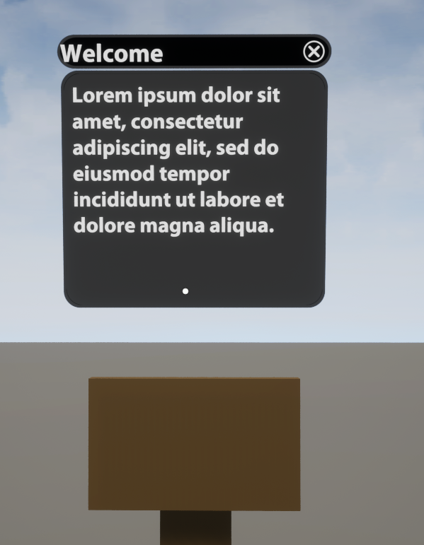
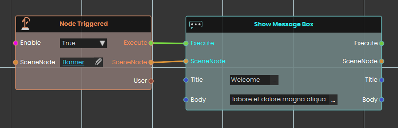
 Message Box \ Hide Message Box
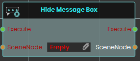
The Hide Message Box node removes an active text panel currently displayed above a specific 3D object. When activated, the node takes the targeted SceneNode input and immediately dismisses its attached message box from the user's view.
 Capture Picture
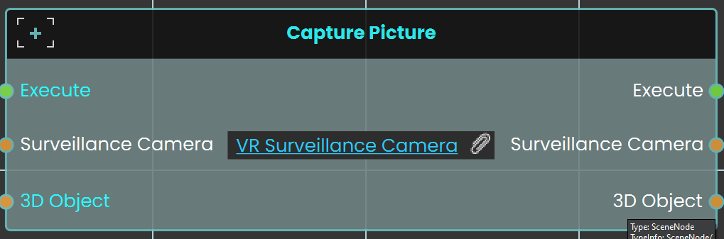
The Capture Picture node is used to capture an image from a camera within the scene, and the captured image can then be displayed on a 3D object within the scene. This allows the user to take snapshots and show them in the VR environment, such as displaying a captured image on a screen or other surface.
Example
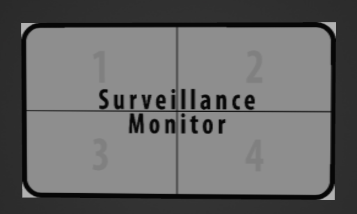
A Surveillance Monitor is first created to display the captured images. This monitor is then attached to the VR camera.
In this example, the Capture Picture Node is used to capture an image on a picture frame model when the user triggers the Activate event. Before that, the Cast SceneNode is used to identify the picture frame as a 3D object, as the Capture Picture Node only works with 3D objects.
 Set Web Browser URL

The Set Web Browser URL node sets the URL for a web browser within the VR Experience. This node enables users to open and navigate to a specified webpage, making it possible to display web content like videos or instructional resources directly within the VR environment.
Example
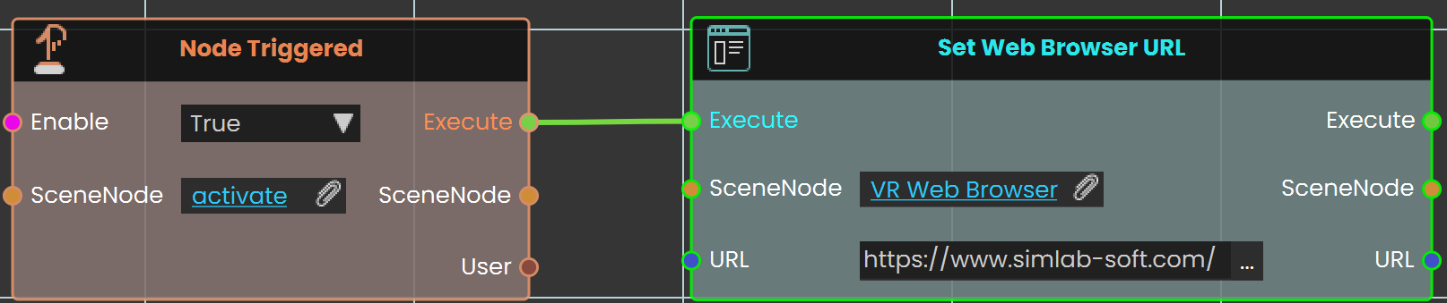

In this example, the Set Web Browser URL node is used to open the SimLab website. The Node Triggered event is activated when the user triggers an object named "activate." As soon as the object is triggered, the Set Web Browser URL node is triggered, setting the URL to the SimLab website. The website then loads and is displayed on a web browser plane within the VR environment.
Media \ Variable Writer \
 Get/Set Variable Writer Color
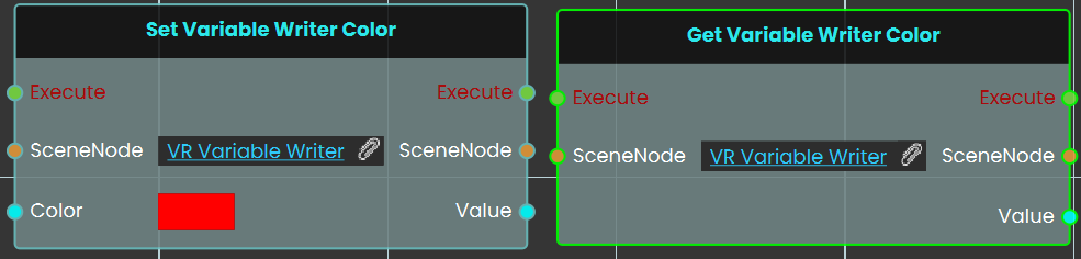
The Set / Get Variable Writer Color nodes are used to control the color of the text displayed by a Variable Writer in the VR environment. The Set node allows you to change the text color dynamically based on events or conditions, while the Get node retrieves the current color of the Variable Writer. This is useful for customizing the visual appearance of displayed values, such as indicating status or drawing attention to changes.
 Get/Set Variable Writer Prefix:
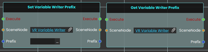
The Set / Get Variable Writer Prefix nodes are used to modify or retrieve the prefix text displayed before the variable value in a Variable Writer. The Set node allows you to add custom text before the value, such as labels or units, while the Get node retrieves the current prefix. This helps provide context to the displayed value, making it clearer for the user.
 Get/Set Variable Writer Suffix:

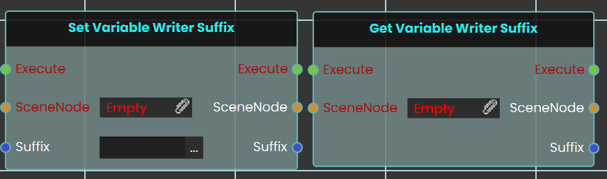
The Set / Get Variable Writer Suffix nodes are used to modify or retrieve the suffix text displayed after the variable value in a Variable Writer. The Set node allows you to add custom text after the value, while the Get node retrieves the current suffix. This helps make the displayed value more informative and user-friendly.
 Get Variable Writer Value
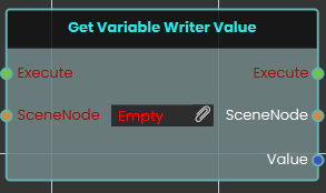
The Get Variable Writer Value node retrieves the pure data value from a designated SceneNode (the target Variable Writer object) and outputs this core Value for use in your logic.
Set Variable Writer Value
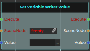
The Set Variable Writer Value node dynamically updates the core data of a target SceneNode (the Variable Writer object). By inputting a new string or numerical Value, the node overrides the writer's pure value while keeping any existing prefixes and suffixes perfectly intact.
 Set Scene Font
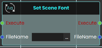
The Set Scene Font node updates the typography globally by changing the font of every Variable Writer object currently present in the VR scene. This node requires the exact FileName of a TrueType Font (.ttf) as its input. To function correctly, the designated .ttf file must first be imported into your project via the Resource Management tab in SimLab Composer.
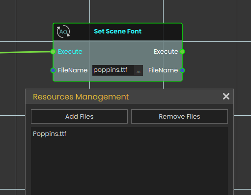
 Set Variable Writer Font
 The Set Variable Writer Font node allows for targeted typography changes by updating the font of a single, specific Variable Writer rather than the entire environment. By assigning the target SceneNode and providing the FileName of a valid
 .ttf font file (previously imported through the Resource Management tab), this node applies the new text style exclusively to the selected object, leaving all other text in the scene unaffected.
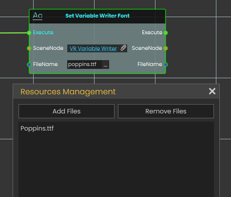
 Set Variable Writer Variable:

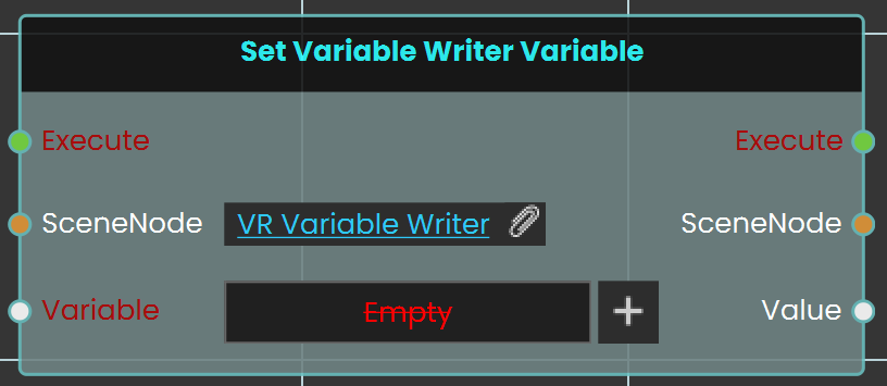
The Set Variable Writer Variable node is used to assign or change the variable displayed by an existing Variable Writer. This allows you to update the displayed content dynamically during the VR experience by switching the linked variable at any time.
Media \ Dynamic Menu
 Set Dynamic Menu Visibility
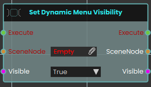
Media \ Sound
 Record Sound
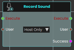
The Record Sound node initiates an audio recording session within the VR experience. This node utilizes a User dropdown parameter to determine whether the system captures microphone audio exclusively from the host or from all participating users. It outputs a Success boolean when the recording successfully starts.
 Set Sound File
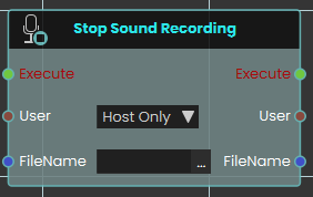
The Stop Sound Recording node halts an active audio recording session. This node requires a specified target User and an exact FileName. Upon execution, it stops the capture process and stores the resulting audio file directly into the project's Resource Management tab under the provided name
 Set Sound Volume
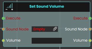
The Set Sound Volume node is used to adjust the audio playback level of a specific 3D sound object within the scene. The numerical Volume input operates strictly within a range of 0 (muted) to 4 (maximum amplification)
 Sound Play
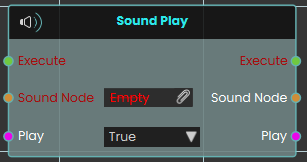
The Sound Play node controls the playback of the audio file stored within a specific 3D sound object. When activated, the node uses the boolean Play input to determine the action for the targeted Sound Node—triggering the sound to start playing from the start of the audio file, or stopping the audio and seeking to the start.
 Sound Seek
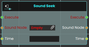
The Sound Seek node instantly jumps to a specific moment within the audio file attached to a 3D sound object. When activated, the node takes the targeted Sound Node and moves its playback position to the exact duration specified by the numerical Time input, measured in seconds.
 Sound Toggle
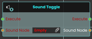
The Sound Toggle node easily switches between playing and pausing a specific 3D sound object in the scene. Once activated, the node evaluates the targeted Sound Node and automatically reverses its current playback status—pausing it if it is currently playing, or playing it if it is currently paused.
 Stop Sound Recording
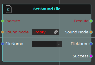
The Set Sound File node dynamically attaches or updates the audio source of a designated Sound Node object in the scene. This node requires the exact FileName of an audio file previously imported into the Resource Management tab, strictly including its file extension (for example, "welcome.mp3"). It outputs a Success boolean to confirm that the sound file was located and attached properly.
Media \ Video
 Set Video File

The Set Video File node allows you to dynamically attach or change the media source of a specific Video Node within your scene. By assigning the target Video Node and inputting the exact FileName of your desired video (such as an .mp4), this node updates the object's media. For this to function correctly, the video file must first be imported into your project through the Resource Management tab. It also outputs a Success boolean to verify that the file was found and loaded.
Example
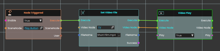
In this example, an interaction is set up to load a short film onto a TV screen and immediately begin playback.
-
Upon interacting with the "Play Button" object, the Node Triggered event initiates the execution flow.
-
The Set Video File node is executed, assigning the previously imported video file "Short Film.mp4" directly to the "TV" video node object.
-
Once the file is successfully attached, the execution flow passes to the Video Play node (with the Play toggle set to True), which instantly starts playing the newly loaded short film on the TV screen.
Set Video URL
Points a video object in your scene at a new video, so it plays from the web address (or file path) you give it.
What it does
This node takes one of the video objects in your scene and tells it which video to play, using the address you provide in the URL. As soon as it runs, the video object switches to that new source — handy for showing different clips on the same screen depending on what the user does.
It only works on a video object; if you point it at any other kind of scene object, nothing changes and the result simply reports that it didn’t succeed. The node hands the same video object straight back out, so you can keep working with it, and it tells you whether the change went through.
Inputs
| Port | Type | What to connect |
|---|---|---|
| Execute | Trigger | Wire this from the previous node’s Execute output. |
| Video Node | Scene node | The video object in your scene whose video you want to change. It must be a video object — other kinds of objects are ignored. |
| URL | Text | The web address (or path) of the video to play, for example https://videos.example.com/safety-intro.mp4. You can leave this empty to clear the current video. |
Outputs
| Port | Type | What you get |
|---|---|---|
| Execute | Trigger | Fires once the node has finished. |
| Video Node | Scene node | The same video object you passed in, so you can connect it to the next node. |
| URL | Text | The video address you supplied, passed straight through. |
| Success | True / false | True if the video object accepted the new video, false if it didn’t (for example, if the object isn’t a video). |
Example
| Video Node input | The Lobby Screen video object in your scene |
| URL input | https://videos.example.com/safety-intro.mp4 |
| Success output | true |
Tips
- Make sure the object you connect is actually a video object — if it isn’t, the change is skipped and Success comes back false.
- Check the Success output before moving on, so you can show a fallback or message if the video couldn’t be loaded.
 Video Play
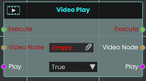
The Video Play node provides direct control over the playback of a Video Node through a boolean Play input. Setting the toggle to True starts the video, while False stops it.
 Video Seek
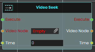
The Video Seek node immediately moves the playback of the target Video Node to a specific Time defined in seconds. It enables precise navigation to any timestamp within the video's total duration.
 Video Toggle
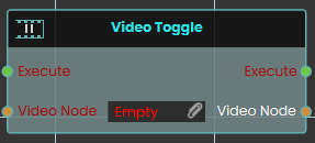
The Video Toggle node switches the playback state of the assigned Video Node between playing and paused. Each execution reverses the current state of the video material, making it ideal for simple play/pause button interactions.
Cloud
 Get Cloud Attribute

The Get Cloud Attribute node enables the user to retrieve saved progress for a specific VR Experience by assigning the attribute in the Attribute Name field. The progress can be saved for either the scene, the user, or both. Once the node is executed, the retrieved value can be acquired through the Result port.
Example

In this example, a Get Cloud Attribute node is used to retrieve stored data from Cloud. When the user enters the object named FinishLine, the object named Scoreboard will be shown. The data saved for this specific scene for all users is retrieved and stored in a variable named Scoreboard, which can then be displayed during the VR Experience.
Set Cloud Attribute

The Set Cloud Attribute node enables the user to store data for a specific VR Experience by assigning the attribute in the Attribute Name field then set the value of it. the data can be stored for either the user, the scene, or both. Once the node is executed, the specified data is saved accordingly.
Example

In this example, a Set Cloud Attribute node is used to store data in Cloud. When the user enters the object named FinishLine, the value of the variable Time will be converted to String and stored under the attribute named Time for the Scene Only, meanwhile the value of the variable Coins_Count will be converted to String and then stored under the attribute Score for the User Only.
Note: To retrieve the Cloud data, the experience must be run from a logged-in account in SimLab VR Viewer.
HTTP Requests
These two nodes let your scene talk to a web service over the internet — for example to fetch some information from a server, send a result to one, or call an online tool. You give the node a web address and a few details about the request; it contacts the server, waits for the reply, and hands you back whatever the server sent. The two nodes are identical except for one thing — the form the reply comes back in:
- Http Request — gives the reply back as a JSON object. Use this when the server answers with JSON.
- Http Request (String) — gives the reply back as plain text. Use this for raw text, or when you'd rather read the text yourself later.
Things to know before you start
These points apply to both nodes.
They wait for the request to finish before carrying on
Talking to a server isn't instant — it can take a moment for the reply to come back. These nodes handle that waiting for you. The node's Execute output does not fire the moment the request is sent; it fires only once the request has finished — that is, once the server has answered or the attempt has failed. So the nodes you wire after this one run when the request comes back, not the instant it goes out, and you don't need to add any delay of your own. The rest of your scene keeps running in the meantime — only this branch waits.
Because the Execute output fires whether the request succeeded or not, always check the result before trusting the reply — see below.
Always check Success before using the reply
A request can go wrong for many reasons — a mistyped address, no internet connection, or the server itself reporting a problem (such as “not found”). That is what the Success output is for. It is Yes only when the server was reached and answered normally; otherwise it is No and the Response comes back empty. Always send Success into a Branch node and only use the Response on the “Yes” side.
The request, in four parts
Every request you send is built from the same few pieces. You set these on the inputs of both nodes:
- Verb — what kind of request it is, chosen from a drop-down. GET (the default) asks the server for something and is by far the most common. POST sends new information to the server; PUT and PATCH update something that already exists; DELETE removes something. (REQUEST is a general-purpose option for unusual cases.) If you are just reading data, leave this on GET.
- URL — the web address to contact, for example
https://api.example.com/status. This is required. - Header (optional) — extra details about the request, given as a JSON object of name-and-value pairs (text values). It is most often used to pass a key or token that proves who you are, such as
{"Authorization": "Bearer abc123"}. - Body (optional) — the information you are sending to the server, given as a JSON object. It is used with POST, PUT, and PATCH. A GET request never carries a body, so anything you connect here is ignored when the verb is GET.
Which one should I use?
Most modern web services answer with JSON. If yours does, use Http Request and you'll get a JSON object you can read straight away with the JSON Object nodes. If the server sends back plain text, or you aren't sure of the format and want the exact text, use Http Request (String). You can always turn text into a JSON object afterwards with Create Json Object From String.
Http Request
Sends a request to a web address and gives you the server's reply as a JSON object.
What it does
This is the node to reach for when the server answers with JSON, which most web services do. It contacts the address you give it, waits for the reply, and reads that reply into a JSON object — so you can pull values straight out of it with the Get Json Object Field nodes on the JSON Objects page. Only the reply's content comes back; this node doesn't hand you the technical status number separately. Remember to check Success first: if the request failed, or the reply wasn't valid JSON, Success is No and the Response is empty.
Inputs
| Port | Type | What to connect |
|---|---|---|
| Execute | Trigger | Wire this from the previous node's Execute output. |
| Verb | Choice | The kind of request: GET, POST, DELETE, PUT, REQUEST, or PATCH. Defaults to GET. |
| URL | Text | The web address to contact. |
| Header | JSON object | Optional. Extra request details as name-and-value pairs, such as an authorization key. |
| Body | JSON object | Optional. The information to send to the server. Used with POST, PUT, and PATCH; ignored for GET. |
Outputs
| Port | Type | What you get |
|---|---|---|
| Execute | Trigger | Fires once the request finishes — whether it succeeded or not. |
| Success | True / false | Yes if the server was reached, answered normally, and the reply could be read as JSON; No otherwise. |
| Response | JSON object | The server's reply, as a JSON object. Empty when Success is No. |
Example
| Verb input | GET |
| URL input | https://api.example.com/weather?city=Dubai |
| Header input | {"Accept": "application/json"} — optional |
| Success output | Yes |
| Response output | {"city": "Dubai", "temperature": 41, "unit": "C"} |
Tips
- Check Success first. Wire Success into a Branch node and only read the Response when it's Yes. A server error such as “not found” counts as No.
- Read one value out. Wire the Response into a Get Json Object Field node with the field name to pull a single value (for example
temperature) out of the reply. - Sending data? Fill in the Body and choose POST (or PUT / PATCH). When a body is sent, the request is automatically marked as JSON for you.
- Reply isn't JSON? If the server sends plain text rather than JSON, use Http Request (String) below instead.
Http Request (String)
Sends the same kind of request, but gives you the server's reply as plain text.
What it does
Works exactly like Http Request, with one difference: the reply comes back as a piece of text, exactly as the server sent it, instead of being read into a JSON object. Use this when the server returns plain text, when the reply isn't JSON, or when you simply want the raw text to store, display, or read yourself later. As with the other node, check Success first; if the request failed, Success is No and the text comes back empty.
Inputs
| Port | Type | What to connect |
|---|---|---|
| Execute | Trigger | Wire this from the previous node's Execute output. |
| Verb | Choice | The kind of request: GET, POST, DELETE, PUT, REQUEST, or PATCH. Defaults to GET. |
| URL | Text | The web address to contact. |
| Header | JSON object | Optional. Extra request details as name-and-value pairs, such as an authorization key. |
| Body | JSON object | Optional. The information to send to the server. Used with POST, PUT, and PATCH; ignored for GET. |
Outputs
| Port | Type | What you get |
|---|---|---|
| Execute | Trigger | Fires once the request finishes — whether it succeeded or not. |
| Success | True / false | Yes if the server was reached and answered normally; No otherwise. |
| Response | Text | The server's reply, as plain text. Empty when Success is No. |
Example
| Verb input | GET |
| URL input | https://api.example.com/version |
| Success output | Yes |
| Response output | v2.4.1 |
Tips
- Check Success first. Wire Success into a Branch node and only read the Response when it's Yes. A server error such as “not found” counts as No.
- Good for non-JSON replies. Plain text, a version number, a short status word, or a line of CSV all come back cleanly as text.
- Text that's really JSON? If the reply happens to be JSON and you want to read fields out of it, pass the Response into Create Json Object From String — or just use Http Request above, which does that step for you.
Related
- JSON Objects — build the Header and Body objects you send, and read values out of the reply from Http Request.
- Create Json Object From String — turn the text from Http Request (String) into a JSON object.
- Branch — use the Success output to decide what happens next.
Scene
 Load Scene
The Load Scene node is used to teleport between different scenes within your VR Experience. Enhancing the overall immersion and interactivity of the experience.
Example
In this example, the Load Scene Node is used to transition the user from one scene to another. This node facilitates changing scenes, allowing for a dynamic experience as users navigate through different environments within the VR application.
 Home Scene
The Home Scene node enables users to return to the initial scene of the VR Experience. This node provides a straightforward way for users to reset the VR Experience to the starting point, ensuring a user-friendly navigation experience.
Example
In this example, the Home Scene Node is used to return the user to the main scene when the trigger event occurs. This allows you to teleport back to the primary environment, enhancing the user experience by providing a clear and intuitive way to return to the starting point.
 Import Scene
The Import Scene node is used to load an external scene into the current VR Experience. This allows users to dynamically bring in additional environments, objects, or elements as needed during runtime.
Example
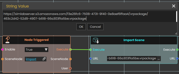
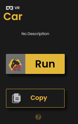
In this example, the Import Scene node is used to load a car model into the scene when the "Import" object is triggered. The Node Triggered event detects user interaction and executes the Import Scene node, which then loads the specified car model from an external VR package file. This allows the car to appear dynamically within the VR environment.
Reload Scene
Restarts the scene that is currently running, bringing it back to the way it was at the start.
What it does
When this node runs, it reloads the current scene from the beginning. Everything in the scene starts over — objects return to their starting positions and the scene plays as if it had just been opened.
It’s a handy way to give the user a “start over” or “try again” option, such as a reset button that puts a training exercise back to the beginning.
Inputs
| Port | Type | What to connect |
|---|---|---|
| Execute | Trigger | Wire this from the previous node’s Execute output — for example, from a button click or another action that should restart the scene. |
Outputs
This node has no outputs.
Example
| Execute input | Wired from a “Restart” button so that clicking it starts the scene over from the beginning. |
Tips
- Reloading starts the scene over completely, so any progress the user has made will be lost — use it when you want a clean fresh start.
- This node has no Execute output, so it’s always the last step in its chain — nothing runs after it.
Enterprise VR Packages
An Enterprise VR Package is a complete VR experience saved as a single, protected .evrpackage file. These packages are encrypted, so only a viewer that has the matching enterprise key can unlock and open them, and creating them is part of a SimLab Enterprise licence. The node below brings one of these packages into the running Viewer and adds it to the main menu, ready to be opened.
Add Enterprise VR Package To Viewer
Fetches an Enterprise VR Package from a web address, unlocks it, and adds it to the Viewer's main menu.
What it does
Give this node the address of an Enterprise VR Package (an .evrpackage file) and, while your experience is running, it downloads the package, unlocks it with its enterprise key, and adds it to the Viewer's main menu — the list of experiences someone can open. The package is stored locally on the device, so from then on it can be opened from the menu like any other entry.
It does not put anything into the scene that's currently playing. This node makes a whole package available to open from the menu; it does not drop models or other content into the running scene. If what you want is to bring content into the current scene, use the Import node instead — that's what it's for.
Because these packages are protected, this only works with genuine Enterprise VR Packages, and the Viewer has to be able to unlock the file. The Success output tells you whether the package was added.
It waits until the package is ready
Downloading a package and unlocking it isn't instant — it takes a moment, and it happens quietly in the background so the rest of your experience keeps running. This node handles that waiting for you. Its Execute output does not fire the moment the node runs; it fires only once the package has been added to the menu or the attempt has failed. So the nodes you wire after this one run when the package is ready, not the instant it's requested, and you don't need to add any delay of your own. Because Execute fires whether it worked or not, always check Success first.
Inputs
| Port | Type | What to connect |
|---|---|---|
| Execute | Trigger | Wire this from the previous node's Execute output. |
| URL | Text | The web address of the Enterprise VR Package (an .evrpackage file) to add. A local file path on the device also works. |
Outputs
| Port | Type | What you get |
|---|---|---|
| Execute | Trigger | Fires once the node has finished — whether the package was added or not. |
| Success | True / false | Yes if the package was downloaded, unlocked, and added to the main menu; No otherwise — for example the address was wrong, the download couldn't be completed, or the package couldn't be unlocked. |
Example
| URL input | https://enterprise.example.com/packages/assembly-training.evrpackage |
| Success output | Yes — the package now appears in the Viewer's main menu |
Tips
Scene actions
These nodes work with the experience that’s currently running — finding out which scene is open, returning to the home screen, saving how the scene looks, and sending the scene back to the cloud. None of them change what’s in your scene; they read from it or move the viewer somewhere else.
Get Running Scene GUID
Gives you the unique ID of the scene that is currently running.
What it does
Every scene (VR package) has its own unique ID — a long piece of text that no other scene shares. This node hands you that ID for the scene that is open and running right now.
It only reads the ID; it doesn’t change anything about the scene. You can use the result to tell scenes apart, to label saved data so you know which scene it came from, or to pass along to other nodes that need to know which scene is loaded.
Inputs
| Port | Type | What to connect |
|---|---|---|
| Execute | Trigger | Wire this from the previous node’s Execute output. |
Outputs
| Port | Type | What you get |
|---|---|---|
| Execute | Trigger | Fires once the node has finished. |
| Result | Text | The unique ID of the scene that is currently running, as text. |
Example
| Result output | 3f2a9c7e-1b4d-4e8a-9c2f-7a1e5d6b0c84 |
Tips
- Two different scenes always have different IDs, so this is a reliable way to check which scene is loaded before running scene-specific steps.
- The exact text will look different for every scene — treat it as a label to match or store, not something to read by eye.
Home Screen
Takes the viewer back to the application’s home screen — the main start screen they see when SimLab Composer first opens.
What it does
When this node runs, it closes out of the current scene and returns the viewer to the home screen, where they can choose what to open next. Think of it as a “back to the main menu” button you can trigger from your scripting.
This node doesn’t change or delete anything in your scene — it simply switches the view back to the home screen. Note that this is different from the Home Scene node, which moves to the home scene inside the content you have open rather than leaving for the main screen.
Inputs
| Port | Type | What to connect |
|---|---|---|
| Execute | Trigger | Wire this from the previous node’s Execute output. The moment it fires, the viewer is taken back to the home screen. |
Outputs
This node has no outputs.
Example
| Execute input | Connect this to a “Quit” or “Exit to menu” button so that pressing it returns the viewer to the home screen. |
Tips
- Use this when a training session is finished and you want the viewer returned to the main screen rather than left in the scene.
- If you only want to jump to the home scene within the open content, use the Home Scene node instead.
Save Visual Settings
Saves how your scene currently looks — its lighting and environment, color adjustments, background, and the appearance of every material — to a visual-settings file (a .vis file) you can import back into SimLab Composer to re-apply that look.
What it does
This node takes a snapshot of the scene’s current visual style and stores it under the name you give it. The snapshot covers the lighting and environment (sun and sky, the surrounding environment light, and fog), the color and exposure adjustments (such as contrast, saturation, white balance, tint, and overall brightness), the background (whether it’s an image, the environment, or a solid color), and how every material in the scene looks (its color, shininess, transparency, reflection, and similar settings).
Saving doesn’t change your scene at all — it only reads the current values and stores them, so everything keeps looking exactly the same. The settings are written to a visual-settings file (a .vis file) named after the name you provide; saving again with the same name replaces the earlier file. Leaving the name empty saves it under a default name.
Applying a saved look
The .vis file this node creates can be imported back into SimLab Composer to apply the saved look to the scene. Save and import it within the same session — don’t close and reopen the scene in between. The saved look is tied to the scene’s internal IDs, and those can change when the scene is reopened, so a file saved in an earlier session may not apply correctly.
Inputs
| Port | Type | What to connect |
|---|---|---|
| Execute | Trigger | Wire this from the previous node’s Execute output. |
| Name | Text | The name for the visual-settings file to create, such as Daytime (saved as Daytime.vis). If you leave it empty, a default name is used. Saving again with the same name replaces the earlier file. |
Outputs
| Port | Type | What you get |
|---|---|---|
| Execute | Trigger | Fires once the node has finished. |
| Name | Text | The same name you provided, passed along so you can reuse it in later nodes. |
Example
| Name input | Daytime |
| Name output | Daytime |
Tips
- Save and import in the same session. Apply the
.visfile before closing and reopening the scene — if the scene is reopened first, its internal IDs may have changed and the saved look might not apply correctly. - Give each look a clear, memorable name (for example
Daytime,Night, orSunset) so it’s easy to recognize when you import it back into Composer. - Reusing a name on purpose is a handy way to update a saved look — the new save simply replaces the earlier
.visfile under that name.
ShareBack Scene
Sends the current scene back to the cloud, saving your changes as a new version of the experience it came from.
What it does
When this node runs, the Viewer shows a “Share Back Scene” prompt and the current scene is saved up to the cloud as a new version of the original experience it was opened from. This lets the changes the viewer made travel back to the shared cloud copy of the experience.
The node waits for the save to finish before it continues, so its result is ready by the time the next node runs. The Success output then tells you whether it worked: true if the scene was saved back as a new version, or false if it couldn’t be shared back right now. This does not change the scene that is currently running — it just publishes a copy back to the cloud.
Inputs
| Port | Type | What to connect |
|---|---|---|
| Execute | Trigger | Wire this from the previous node’s Execute output, for example from a button the viewer presses when they want to send their changes back. |
Outputs
| Port | Type | What you get |
|---|---|---|
| Execute | Trigger | Fires once the scene has finished being shared back — whether it succeeded or not. Check Success before assuming the save worked. |
| Success | True / false | true if the scene was saved back to the cloud as a new version; false if it couldn’t be shared back — for instance if the scene didn’t come from the cloud, the viewer isn’t signed in or doesn’t have permission to update it, or there’s no connection. |
Example
| Execute input | Wired from a “Save my changes” button in the scene |
| Execute output | Continues to a Branch node that reacts based on Success |
| Success output | true |
Tips
- Because the Execute output fires whether the save worked or not, check the Success output first — a Branch node is a handy way to show a “Saved!” message on
trueand a “Couldn’t save” message onfalse. - This only works for scenes that were opened from a cloud experience, and the viewer needs to be signed in with permission to update it.
Integration
Open External Connection
SimLab Composer 14 introduces WebSocket support, enabling seamless integration with external systems allowing it to work with external hardware, co-simulation engines, and websites, unlocking numerous possibilities.
The WebSocket nodes (Open External Connection, Send Message, and On Message Received) are exclusively available in the Ultimate Edition.
The Open External Connection node enables the opening of a WebSocket connection to an external system. When the Auto Handle Lua is set to true, incoming messages containing Lua scripts will be automatically executed. This allows for real-time interaction between SimLab Composer and external systems, such as co-simulation engines or hardware, with the ability to dynamically execute Lua code as part of the interaction.
Input Ports:
- Execute
- URL: WebSocket URL that includes the server IP address, port, channel (optional). Example: ws://server1.simlab-soft.com:8765/robots_1
- Auto Handle Lua: Incoming messages containing Lua scripts will automatically execute those scripts If enabled (True).
Output Ports:
- Execute
- URL
- Auto Handle Lua
 Report Completed
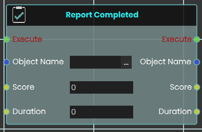
The Report Completed node functions similarly to the Report Score node, but it records both a score and a completion time simultaneously. It is ideal for finalizing tasks, exams, or training scenarios where both accuracy and speed are evaluated. Like the Report Score node, the recorded data is safely stored and utilized within the SimLab VR Assessment Portal for instructor review.
Key parameters:
-
Object Name: The name of the exam, task, or entity being evaluated.
-
Score: The numerical score or grade achieved.
-
Duration: The total time taken to complete the evaluated task.
 Report Score
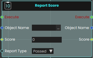
The Report Score node enables the system to register and record a specific value as a score when the node is executed. This is highly useful for tracking user performance, evaluating task completion, or logging quiz results within a training scenario.
The node utilizes the following key parameters to define the recorded data:
-
Object Name: Specifies the name of the exam, task, or specific entity being evaluated.
-
Score: The numerical input field where the final score value is passed or entered.
-
Report Type: A dropdown menu that determines the classification or outcome of the score. The available options are Passed, Scored, and Failed.
The node stores the score and its associated information to be used primarily in the SimLab VR Assessment Portal, where instructors and administrators can securely view and evaluate the reported values.
Example
In this example, the system records a student's final score the moment they finish a test.
-
Upon interacting with the "Finish Quiz" object, the Node Triggered event initiates the execution flow.
-
The Number Variable Value node is used to retrieve the current numerical value stored in the
FinalScorevariable. -
This retrieved value is passed directly into the Score input of the Report Score node.
-
The Report Score node is configured with the Object Name set to "Student Final Score" and the Report Type set to "Scored," which officially logs the student's result into the system's evaluation records when executed.
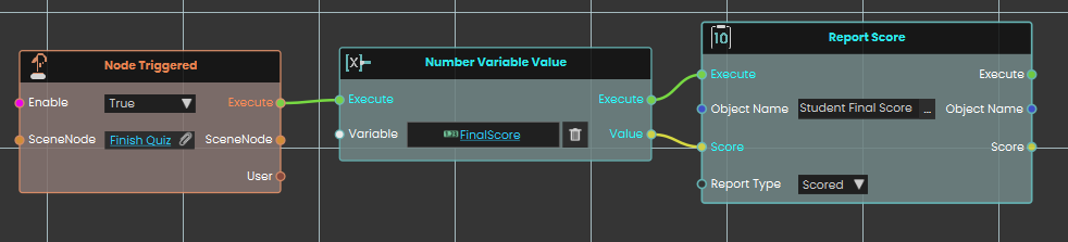
Send Message
The Send Message node allows you to communicate with the WebSocket server by sending messages. It is essential to ensure that the message format follows the protocol that the server and other clients can process. This node enables real-time interaction with external systems, making it possible to transmit data or commands to connected servers or clients.
Input Ports:
- Executive
- URL: WebSocket URL that includes the server IP address, port, and channel (optional). Example: ws://server1.simlab-soft.com:8765/robots_1
- Message
Output Ports:
- Execute
- URL
- Message
SceneNode \ Snapping
 Can Snap Node

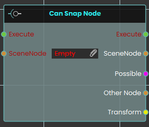
The Can Snap Node checks whether a specific SceneNode is currently within the eligible snapping range of another object. This node evaluates the spatial relationship between objects and outputs a "Possible" boolean to confirm if a snap can occur, alongside referencing the "Other Node" and its spatial "Transform" data for further logic use.
 Snap Node

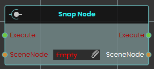
The Snap Node instantly snaps a designated SceneNode directly to the nearest eligible target socket or node. Executing this node forces the object to immediately align and attach itself to the valid snapping destination without any transition time.
 Snap Node (Animated)
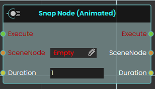
The Snap Node (Animated) securely aligns and attaches a SceneNode to its nearest eligible target, but does so with a smooth visual transition. This node utilizes a "Duration" input to smoothly interpolate the object's movement into its snapped position over the specified number of seconds, rather than snapping instantly.
SceneNode \ Hierarchy
 Get Node Children
The Get Node Children enables the user to retrieve child SceneNodes from a specified parent node within the hierarchy in the scene browser. This function allows users to access the children of a parent node in the VR environment, facilitating more complex interactions and hierarchies.
Example
In this example, the Get Node Children enables the user to retrieve the child of a group named "Ball Parent" on the Trigger event. When the user triggers the Activate object, the Get Node Children retrieves the child node, and the Get Node Attribute (String) is used to acquire the child’s attribute.
 Reset Parent Node
The Reset Parent Node enables the user to reset all transformations applied to an object and return it to its original position relative to its main parent. This can be done by linking the node to an event or condition within the scene. Once the reset is executed, the object will revert to its default state under the main parent.
Example
In this example, a Reset Parent Node is used to reset the transformations of a car object to its original state relative to its main parent once the "Car Move" sequence ends. When the user triggers the Activate object, the car move animation sequence will play. After the sequence concludes, the Reset Parent Node is triggered automatically, returning the car to its default position under the main parent.
Get Node Descendants
Gives you every node nested underneath a scene node — not just its direct children, but everything below it at any depth.
What it does
Point this node at a scene node (often a group or assembly) and it hands back all of the nodes contained inside it: its children, their children, and so on all the way down. It’s like asking “give me everything inside this, no matter how deeply it’s tucked away.” This is the difference between this node and Get Node Children, which only returns the items one level down.
It simply reads the scene and reports back — nothing is moved, regrouped, or changed. The scene node you started from also comes straight back out, so you can keep wiring from it.
Inputs
| Port | Type | What to connect |
|---|---|---|
| Execute | Trigger | Wire this from the previous node’s Execute output. |
| SceneNode | Scene node | The node whose contents you want — usually a group or assembly. Everything nested inside it will be returned. |
Outputs
| Port | Type | What you get |
|---|---|---|
| Execute | Trigger | Fires once the node has finished. |
| SceneNode | Scene node | The same scene node you connected, passed straight back out unchanged so you can keep wiring from it. |
| Descendants | Scene node | Every node nested inside the one you gave — children, grandchildren, and deeper — gathered together. Connect this to a node that works through each one in turn. |
Example
| SceneNode input | A group named Engine Assembly |
| SceneNode output | The same Engine Assembly group, unchanged |
| Descendants output | Every part inside it at any level — Block, Cylinder Head, the bolts grouped under it, and so on |
Tips
- Use this when you want to reach everything inside a group, including items nested several levels deep. If you only need the items directly under a node, use Get Node Children instead.
- The Descendants output is a collection of many nodes, so it pairs well with a node that loops through or acts on each one — for example to hide, color, or move every part inside an assembly at once.
Get Parent Node
Finds the object that a scene node sits inside — its parent in the scene tree.
What it does
Scene objects can be nested: a wheel might sit inside a car, which sits inside a group. This node takes one object and gives you back the object directly above it in that nesting — the thing it belongs to.
It only looks the parent up; it doesn't move or change anything in your scene. You also get the original object handed straight back, so you can keep working with both the object and its parent. If the object is at the very top of the scene and isn't inside anything, the Parent result will be empty.
Inputs
| Port | Type | What to connect |
|---|---|---|
| Execute | Trigger | Wire this from the previous node’s Execute output. |
| SceneNode | Scene node | The object whose parent you want to find. |
Outputs
| Port | Type | What you get |
|---|---|---|
| Execute | Trigger | Fires once the node has finished. |
| SceneNode | Scene node | The same object you connected in, passed straight back so you can keep wiring from it. |
| Parent | Scene node | The object that the input object sits inside. Empty if the object is at the top level and isn’t inside anything. |
Example
| SceneNode input | Front Left Wheel |
| SceneNode output | Front Left Wheel (handed back unchanged) |
| Parent output | Car Body |
Tips
- Always check whether the Parent result is empty before using it — a top-level object has no parent to return.
- Because the original object comes back out unchanged, you can chain this node and keep building from the same object further down your script.
Set Parent Node
Moves a scene node so it becomes a child of another node, changing how the two move and behave together.
What it does
In your scene, nodes are arranged in a parent-and-child tree. When one node is the child of another, it travels with its parent — move, rotate, or hide the parent and the child follows along. This node lets you set (or change) which node a given scene node belongs to.
You give it the node you want to move and the node that should become its new parent. It places the first node under the second, then hands both nodes back out so you can keep wiring from them. It only changes the parent-child relationship — the node itself, along with its name and contents, stays the same.
Inputs
| Port | Type | What to connect |
|---|---|---|
| Execute | Trigger | Wire this from the previous node’s Execute output. |
| SceneNode | Scene node | The node you want to move — the one that will become a child. |
| Parent | Scene node | The node that should become the new parent. The node above will be placed under it. |
Outputs
| Port | Type | What you get |
|---|---|---|
| Execute | Trigger | Fires once the node has finished. |
| SceneNode | Scene node | The same node you sent in, passed straight back out so you can keep wiring from it. |
| Parent | Scene node | The same parent node you sent in, passed straight back out so you can keep wiring from it. |
Example
| SceneNode input | Wheel_FrontLeft |
| Parent input | Car_Body |
| SceneNode output | Wheel_FrontLeft — now a child of Car_Body, so it moves with the car body from here on |
| Parent output | Car_Body |
Tips
- This is handy for grouping things together at runtime — for example, attaching a tool to a hand so it follows the hand’s movement.
- The child keeps its place in the scene; only what it is attached to changes.
SceneNode \ Appearance
 Is Node Visible
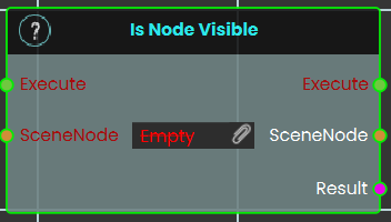
This node checks the current visibility state of a specified 3D object within the VR Viewer. It evaluates whether the targeted object is currently rendered (shown) or hidden in the scene, and outputs this status as a boolean value (True or False).
Example:
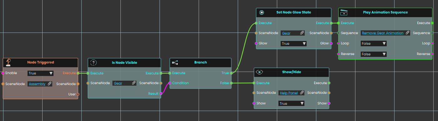
In this example, triggering the "Assembly" object prompts the system to check if the "Gear" node is currently visible. If the gear is visible, the True branch executes, setting the gear to glow and playing a "Remove Gear" animation sequence. However, if the gear is already hidden, the False branch executes instead, displaying a "Help Panel" to the user.
Get Node Material
Finds out which material is currently applied to a 3D object in your scene.
What it does
Point this node at a 3D object and it hands you back the material that is currently on it — the look that gives the object its color, texture, shininess, and so on. You can then pass that material to another object, inspect it, or change it elsewhere in your script.
This only reads the object’s material; it doesn’t change the object or its appearance in any way. The same object comes straight back out so you can keep wiring more steps from it.
Inputs
| Port | Type | What to connect |
|---|---|---|
| Execute | Trigger | Wire this from the previous node’s Execute output. |
| SceneNode | Scene node | The 3D object whose material you want to read. |
Outputs
| Port | Type | What you get |
|---|---|---|
| Execute | Trigger | Fires once the node has finished. |
| SceneNode | Scene node | The same object you connected, passed straight back out so you can keep wiring from it. |
| Material | Material | The material currently applied to that object. |
Example
| SceneNode input | Car Body |
| SceneNode output | Car Body (unchanged) |
| Material output | Red Glossy Paint |
Tips
- Use this to copy a look from one object to another: read the material here, then apply it to a different object with a “Set Node Material” node.
Set Node Glow State
Turns a glowing highlight on or off for an object in your scene.
What it does
This node takes an object from your scene and switches its glow effect on or off. Use it to make something stand out — for example, lighting up the part a trainee needs to pick up next, or highlighting a button they should press.
It only changes whether the glow is showing; nothing else about the object is altered. The same object is handed straight back out so you can keep wiring more actions onto it.
Inputs
| Port | Type | What to connect |
|---|---|---|
| Execute | Trigger | Wire this from the previous node’s Execute output. |
| SceneNode | Scene node | The object in your scene you want to glow (or stop glowing). |
| Glow | True / false | Set to true to turn the glow on, or false to turn it off. Defaults to true if you leave it unconnected. |
Outputs
| Port | Type | What you get |
|---|---|---|
| Execute | Trigger | Fires once the node has finished. |
| SceneNode | Scene node | The same object you sent in, passed straight back out so you can keep wiring from it. |
| Glow | True / false | The glow setting you applied (true or false), passed along. |
Example
| SceneNode input | The Wrench object the trainee needs to find next |
| Glow input | true |
| SceneNode output | The same Wrench object, now glowing |
| Glow output | true |
Tips
- To turn a highlight off later, run this node again on the same object with Glow set to
false. - Because the object comes straight back out, you can chain another action right after — for example, glow it and then play a sound.
Set Node Material
Gives a scene object a new look by applying a material to it.
What it does
This node takes one of your scene objects and a material, and puts that material onto the object — changing how it looks (its color, texture, shininess, and so on). For example, you could switch a part from a plain gray finish to a glossy red one.
The object itself is the same object as before — only its appearance changes. The node hands the object and the material straight back out, so you can keep wiring more steps from either of them.
Inputs
| Port | Type | What to connect |
|---|---|---|
| Execute | Trigger | Wire this from the previous node’s Execute output. |
| SceneNode | Scene node | The object in your scene whose look you want to change. |
| Material | Material | The material to put on the object — the new color, texture, and finish it should have. |
Outputs
| Port | Type | What you get |
|---|---|---|
| Execute | Trigger | Fires once the node has finished. |
| SceneNode | Scene node | The same object you sent in, passed straight back out so you can keep wiring from it. |
| Material | Material | The same material you sent in, passed back out in case you want to use it again. |
Example
| SceneNode input | Car_Body |
| Material input | Glossy_Red |
| SceneNode output | Car_Body — now showing the glossy red finish, ready to wire into the next step |
Tips
- Prepare the materials you want to switch between in your scene first, then feed the right one into this node when you want the object to change.
- Because the object comes straight back out, you can chain several changes — for example, set a material and then move or highlight the same object in the next node.
Show/Hide
Shows or hides a scene node, so you can make objects appear and disappear during your scene.
What it does
Give this node a scene node and a true/false value. When set to true, the node becomes visible; when set to false, it is hidden from view. This is handy for revealing a part once a step is reached, or hiding a finished assembly to clear the workspace.
Hiding a node only changes whether it can be seen — the object itself stays in your scene, keeps its position, and can be shown again at any time. The same scene node comes straight back out so you can keep wiring more actions from it.
Inputs
| Port | Type | What to connect |
|---|---|---|
| Execute | Trigger | Wire this from the previous node’s Execute output. |
| SceneNode | Scene node | The object you want to show or hide, such as a part, group, or model in your scene. |
| Show | True / false | Set to true to make the object visible, or false to hide it. |
Outputs
| Port | Type | What you get |
|---|---|---|
| Execute | Trigger | Fires once the node has finished. |
| SceneNode | Scene node | The same scene node you passed in, handed straight back so you can keep wiring more actions from it. |
| Show | True / false | The same true/false value you passed in, so you can reuse it further along. |
Example
| SceneNode input | Warning_Light |
| Show input | true — the warning light appears to alert the trainee |
| SceneNode output | Warning_Light, passed straight back so you can move or color it next |
Tips
- To hide an object, set Show to
false; to bring it back, run the node again withtrue. - A hidden object is only invisible — it is still in your scene and keeps its place, so showing it again puts it right back where it was.
SceneNode \ Curve
The Curve nodes let you draw and control 3D lines directly inside the VR scene. A curve is a single line that runs through a series of points you place in 3D space, which makes it ideal for things like paths, routes, connectors, graphs, and live data visualizations. You start by creating a named curve, then add points to it one at a time; later you can move or remove individual points, or change the line's thickness and style at any moment.
Every curve has a unique Name, and that name is how all of the other curve nodes find the line they should act on. As you add points, each one is given a number called its Index. Point numbering starts at 1 — the first point you add is point 1, not point 0 — and that number is what the Remove Curve Point and Update Curve Point nodes use to target a specific point.
 Create Curve
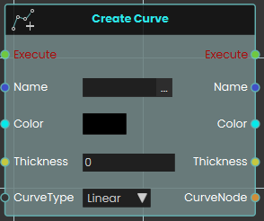
The Create Curve node initializes a new 3D cylindrical line within the VR scene. This is highly useful for creating dynamic visual elements like charts, graphs, or data visualizations.
When activated, it generates a base curve using four primary inputs: a unique text Name (which acts as an identifier required by all other curve-related nodes to target this specific line), a Color, a numerical Thickness value, and a CurveType dropdown that dictates whether the overall line behaves as a smooth curve or rigid straight lines. It then outputs a reference to the newly created CurveNode to continue the logic flow.
 Add Curve Point
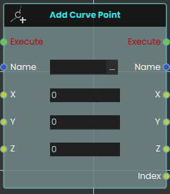
The Add Curve Point node builds upon an existing curve by generating a new point in 3D space. Once activated, the node locates the specific curve identified by the Name input and places a new point at the provided X, Y, and Z coordinates. The system automatically draws a line connecting this newly created point to the previously established point, seamlessly extending the curve. Crucially, this node outputs an Index value—a unique number assigned to this specific point when it is created. Point numbering starts at 1, so the first point you add has an index of 1 (not 0), the second has an index of 2, and so on. This number is the point's permanent identifier, and you use it later to target the point with the Remove Curve Point and Update Curve Point nodes.
Example:
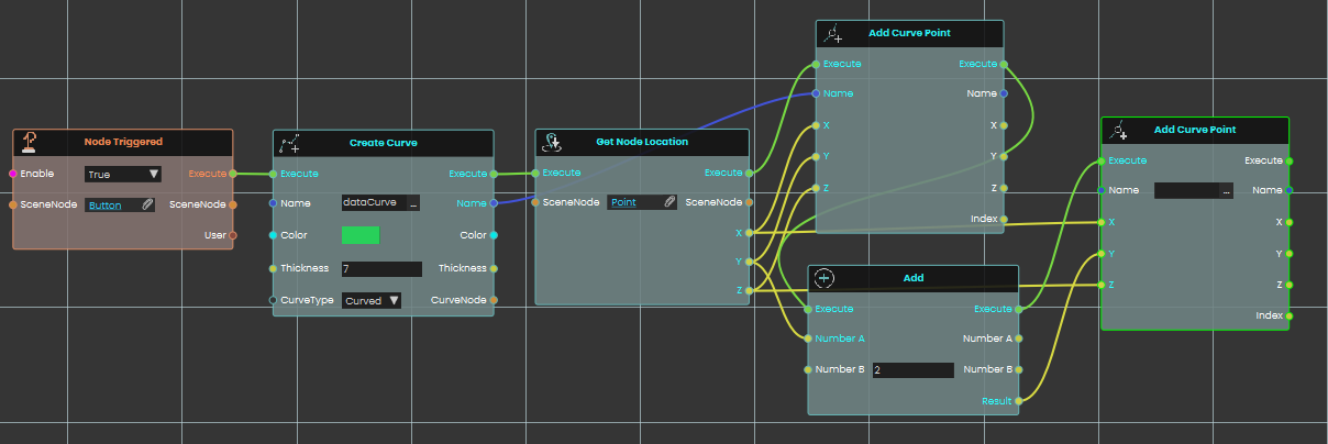
In this expanded example, we build an interaction where clicking a button initializes a new curve and sequentially places two connected points based on a target object's location:
-
A Node Triggered event node continuously listens for the user to interact with a specific "Button" object in the scene.
-
Once the button is clicked, it activates a Create Curve node, which initializes a new curve named "dataCurve" with a distinct green color, a thickness value of 7, and a "Curved" line type.
-
The execution flow immediately proceeds to a Get Node Location node, which retrieves the exact X, Y, and Z spatial coordinates of a target 3D object named "Point".
-
The first Add Curve Point node is activated. It takes the "dataCurve" identifier and utilizes the precise X, Y, and Z coordinates retrieved from the target object to generate the first anchor point of the curve.
-
Simultaneously, an Add math node receives the original Y coordinate from the "Point" object and adds a numerical value of 2 to it.
-
Following the creation of the first point, a second Add Curve Point node is executed. It uses the same "dataCurve" identifier and the original X and Z coordinates, but it uses the newly calculated result from the Add node (Y + 2) for its vertical placement. This generates a second point exactly 2 units directly above the first, automatically drawing a connected line between them.
 Remove Curve Point
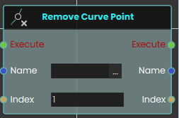
The Remove Curve Point node is used to permanently delete a specific point from an active curve. Once activated, it takes the curve's Name and the specific Index number of the point you wish to erase. Keep in mind that point numbering starts at 1, so an Index of 1 targets the first point of the curve, not the second — this is the same number that the Add Curve Point node returned when the point was created. Upon deletion, the curve automatically bridges the gap between the remaining adjacent points to maintain a continuous, unbroken line.
 Set Curve Thickness

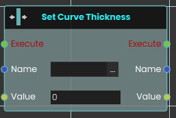
The Set Curve Thickness node dynamically adjusts the physical width of an existing curve during the VR experience. When activated, it targets the curve specified by the Name input and instantly changes its visual bulk to match the number provided in the Value input, allowing you to easily scale the visual prominence of the line on the fly.
 Set Curve Type

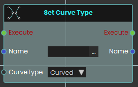
The Set Curve Type node instantly alters how the connections between a curve's points are visually rendered in the scene. Once activated, it locates the curve by its Name and applies the newly selected CurveType from the dropdown menu. This allows you to toggle a curve between "Curved" (which renders smooth, sweeping connections between the points) and "Linear" (which renders sharp, perfectly straight lines between the points) at any time.
 Update Curve Point

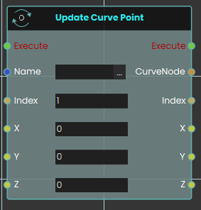
The Update Curve Point node allows you to dynamically change the 3D location of a previously created point on an existing curve. When activated, it targets the curve using the Name input and isolates a specific point using its numerical Index value. As with the other curve nodes, this Index starts at 1 (the first point is index 1, not 0) and matches the value that Add Curve Point returned when the point was added. It then instantly moves that point to the newly provided X, Y, and Z coordinates. The line connecting the points will automatically recalculate and redraw itself to reflect the point's new location in the scene.
Device / Attributes
A device attribute is a named value saved on the device the experience is running on — a PC, a phone or tablet, a standalone VR headset, and so on. You give each value a name (for example language) and store a piece of text under it. These values belong to the device itself: they stay on it after the scene or app is closed and reopened (even across different experiences), they are not tied to whoever is signed in, and the person using the device can also see and change them in the viewer’s Settings.
That makes device attributes the right tool for remembering something on one particular device for next time — a chosen language, measurement units, the name of a kiosk or station, and the like. The examples on this page all use the same running example: a setting named language holding the text English.
What's on this page
- Set Device Attribute (String) — save a piece of text on the device under a name.
- Get Device Attribute (String) — read back the text saved under a name.
- Device Has Attribute — check whether the device has a value saved under a name (true or false).
- Remove Device Attribute — delete a saved value from the device.
Attributes
These four nodes are the complete set for working with a device’s saved values — store one, read it back, check whether it exists, and remove it. None of them is tied to who is signed in, and every value stays on the device for next time.
Set Device Attribute (String)
Saves a piece of text on the device under a name you choose, so you can read it back later — even after the experience is closed and reopened.
What it does
This node stores a bit of text on the device the experience is running on — a PC, a phone or tablet, a standalone VR headset, and so on. You give it a name (such as language) and the text to store (such as English), and the node remembers that value on the device. If a value with that name doesn’t exist yet, it creates one; if it already exists, the new text replaces the old.
The value stays on the device, so it’s still there next time the experience runs — it’s a good way to remember a setting for next time. These values belong to the device itself, not to whoever is signed in, so they aren’t tied to a particular person. They also aren’t hidden: the person using the device can see and change them in the viewer’s Settings.
Inputs
| Port | Type | What to connect |
|---|---|---|
| Execute | Trigger | Wire this from the previous node’s Execute output. |
| Attribute Name | Text | The name to save the text under, such as language. You can pick a name from the drop-down list of names already known on the device, or simply type a brand-new name. |
| Value | Text | The text you want to store, such as English. If a value with this name already exists, this replaces it. |
Outputs
| Port | Type | What you get |
|---|---|---|
| Execute | Trigger | Fires once the node has finished saving the value. |
| Attribute Name | Text | The same attribute name you gave, passed straight through (handy for wiring into the next node). |
| Value | Text | The same text you stored, passed straight through. |
Example
| Attribute Name input | language |
| Value input | English |
| Attribute Name output | language |
| Value output | English |
Tips
- Use this to remember a setting on the device for next time, such as the chosen
languageor measurementunits. - Saving again under the same name simply replaces the old text — you don’t need to remove the old value first.
- Pair it with Get Device Attribute (String) to read the value back later.
Get Device Attribute (String)
Reads back a piece of text that was saved on this device under a name you choose.
What it does
A device attribute is a value stored on the device the experience is running on — a PC, phone, tablet, or VR headset. You give this node the name of the attribute you want, and it hands back the text currently saved under that name. These values live on the device itself, not with whoever is logged in, and they stay put after the scene or app is closed and reopened — so this node is the way to read something you remembered on this device for next time.
This node only reads; it never changes the saved value. If nothing has been saved under that name yet, you simply get back empty text — the node carries on without any error.
Inputs
| Port | Type | What to connect |
|---|---|---|
| Execute | Trigger | Wire this from the previous node’s Execute output. |
| Attribute Name | Text | The name of the value you want to read. Pick one from the drop-down, which lists names already saved on the device, or type a new name yourself. For example, language. |
Outputs
| Port | Type | What you get |
|---|---|---|
| Execute | Trigger | Fires once the node has finished. |
| Attribute Name | Text | The same attribute name you gave, passed straight through (handy for wiring into the next node). |
| Result | Text | The text saved under that name. If nothing is saved under that name, you get back empty text. |
Example
| Attribute Name input | language |
| Attribute Name output | language |
| Result output | English |
Tips
- Getting empty text back usually means nothing has been saved under that name yet — on this device, set it first with Set Device Attribute (String), or check with Device Has Attribute before reading.
- These values are saved per device and are not tied to who is logged in. The person using the device can also see and change them in the viewer’s Settings.
Device Has Attribute
Checks whether this device already has a saved setting with a given name, and tells you yes or no.
What it does
This node looks on the device the experience is running on — a PC, phone, tablet, VR headset, and so on — for a saved setting with the name you give it. If a setting with that name exists, the Result comes back as true; if there is no setting with that name, it comes back as false. Either way the node simply reports what it found and does not change or remove anything.
These device settings live on the device itself. They are not tied to whoever is signed in, and they stay on the device after the scene or app is closed and reopened — even across different experiences. (The person using the device can also view and change them in the viewer’s Settings.) That makes this node handy for asking “has this device been set up before?” so you can decide what to do next.
Inputs
| Port | Type | What to connect |
|---|---|---|
| Execute | Trigger | Wire this from the previous node’s Execute output. |
| Attribute Name | Text | The name of the setting to look for, such as language. The field offers a drop-down of names already saved on the device, and you can also type a brand-new name that isn’t in the list. |
Outputs
| Port | Type | What you get |
|---|---|---|
| Execute | Trigger | Fires once the node has finished — whether the setting was found or not. |
| Attribute Name | Text | The same attribute name you gave, passed straight through (handy for wiring into the next node). |
| Result | True / false | true if the device has a setting with that name, or false if it does not. |
Example
| Attribute Name input | language |
| Attribute Name output | language |
| Result output | true (this device has a language setting saved) |
Tips
- Use this as a quick “first time on this device?” check: if Result is
false, set up a default; if it’strue, just read the saved value. - This node only checks for the setting — it never changes or removes it. Use Set Device Attribute to store a value and Remove Device Attribute to clear one.
Remove Device Attribute
Deletes a saved setting from the device the experience is running on.
What it does
A device attribute is a small named value kept on the device itself — the PC, phone, tablet, or VR headset that is running the experience. These values stay on the device and are saved for next time, so they are still there after the app or scene is closed and reopened. They aren’t tied to who is logged in, and the person using the device can see and change them in the viewer’s Settings. This node removes one of those saved values by name.
Give it the name of the attribute you want to remove. If a value with that name is saved on the device, it is deleted; if no value with that name exists, the node simply does nothing and carries on — no error. The name you gave is passed straight through on the output, so you can keep wiring the flow forward.
Inputs
| Port | Type | What to connect |
|---|---|---|
| Execute | Trigger | Wire this from the previous node’s Execute output. |
| Attribute Name | Text | The name of the device value to remove, such as language. You can pick a name from the drop-down list of values already saved on the device, or type a name yourself. |
Outputs
| Port | Type | What you get |
|---|---|---|
| Execute | Trigger | Fires once the node has finished. |
| Attribute Name | Text | The same attribute name you gave, passed straight through (handy for wiring into the next node). |
Example
| Attribute Name input | language |
| Attribute Name output | language |
Tips
- It’s safe to remove a name that may not be there — if nothing is saved under that name, the node just moves on without an error.
- Removing a value only affects this device. Saved values on other devices are not touched.
SceneNode \ Transform \ Scale
These nodes read and change the size of a 3D object. Size is given as three numbers — X, Y, and Z — each a multiplier of the object’s original size: 1 means unchanged, 2 means twice as big, 0.5 means half. Most come in two forms: a world version that uses the object’s size in the whole scene, and a (Local) version measured relative to its parent or group. Changing an object’s size never moves it or turns it.
What's on this page
- Read the size — find out how large an object currently is.
- Change the size — resize an object, instantly or smoothly over time.
Read the size
These read an object’s current size without changing anything.
Get Node Scale
Reads how large an object currently is in the scene and gives you its size along each axis as separate numbers.
What it does
This node looks at an object you point it to and reports its current size in the whole scene. You get three numbers back — one for the X axis, one for Y, and one for Z. Each number is a multiplier of the object’s original (authored) size: 1 means unchanged, 2 means twice as big, and 0.5 means half size.
It only reads the size — it doesn’t resize the object or change anything else in the scene. The same object is also passed straight through, so you can keep working with it in the nodes that follow.
Inputs
| Port | Type | What to connect |
|---|---|---|
| Execute | Trigger | Wire this from the previous node’s Execute output. |
| SceneNode | Scene node | The object whose size you want to read. Connect the object you picked earlier in the flow. |
Outputs
| Port | Type | What you get |
|---|---|---|
| Execute | Trigger | Fires once the node has finished. |
| SceneNode | Scene node | The same object passed through, so you can chain more nodes after this one. |
| X | Number | The object’s current size along the X axis, as a multiplier of its original size (1 = unchanged). |
| Y | Number | The object’s current size along the Y axis, as a multiplier of its original size. |
| Z | Number | The object’s current size along the Z axis, as a multiplier of its original size. |
Example
| SceneNode input | A crate you placed in the scene |
| X output | 2 |
| Y output | 2 |
| Z output | 0.5 |
Tips
- A value of
1on an axis means that axis is at the object’s original size. Values above1are larger; values below1are smaller. - This reports the object’s overall size in the whole scene, so if the object sits inside a group that has been resized, that resizing is included in the result.
Get Node Scale (Local)
Reads how big an object currently is, measured relative to its parent or group.
What it does
This node looks at one object in your scene and tells you its current size along each axis (X, Y, and Z). Each value is a multiplier of the object’s original, authored size: 1 means unchanged, 2 means twice as big, and 0.5 means half size. It is not a measurement in meters and not a percentage.
The size you get back is the local size — measured relative to the object’s parent or group. If that parent or group is resized, this local value stays the same. (If the object has no parent or group, its local size and its size in the whole scene are the same.) This node only reads the size; it doesn’t change the object or affect anything else in your scene.
Inputs
| Port | Type | What to connect |
|---|---|---|
| Execute | Trigger | Wire this from the previous node’s Execute output. |
| SceneNode | Scene node | The object whose size you want to read. |
Outputs
| Port | Type | What you get |
|---|---|---|
| Execute | Trigger | Fires once the node has finished. |
| SceneNode | Scene node | The same object passed straight through, so you can chain more nodes after this one. |
| X | Number | The size multiplier along the X axis (1 = original size). |
| Y | Number | The size multiplier along the Y axis (1 = original size). |
| Z | Number | The size multiplier along the Z axis (1 = original size). |
Example
| SceneNode input | The crate you placed in the scene |
| X output | 2 |
| Y output | 0.5 |
| Z output | 1.5 |
Tips
- A value of
1on every axis means the object is still at its original, authored size. - To read the object’s size in the whole scene instead of relative to its parent or group, use the matching node without “(Local)” in its name.
Change the size
These resize an object. The plain versions change it instantly; the (Animated) versions grow or shrink it smoothly over a number of seconds.
Set Node Scale
Resizes an object in your scene by setting how big it is along each axis.
What it does
This node changes the size of the object you give it. You set three numbers — X, Y, and Z — and each one is a multiplier of the object’s original, authored size: 1 leaves that axis unchanged, 2 makes it twice as big, and 0.5 makes it half size. The change happens instantly.
The size you set here is the object’s overall size in the whole scene. The same object passes straight out the other side, so you can keep working with it in the next node. Only the object you connect is affected — nothing else in your scene moves or resizes.
Inputs
| Port | Type | What to connect |
|---|---|---|
| Execute | Trigger | Wire this from the previous node’s Execute output. |
| SceneNode | Scene node | The object you want to resize. |
| X | Number | The size multiplier along the X axis. 1 keeps it the same, 2 doubles it, 0.5 halves it. |
| Y | Number | The size multiplier along the Y axis. 1 keeps it the same. |
| Z | Number | The size multiplier along the Z axis. 1 keeps it the same. |
Outputs
| Port | Type | What you get |
|---|---|---|
| Execute | Trigger | Fires once the node has finished. |
| SceneNode | Scene node | The same object, passed through so you can chain more nodes. |
| X | Number | The X multiplier you set, passed through. |
| Y | Number | The Y multiplier you set, passed through. |
| Z | Number | The Z multiplier you set, passed through. |
Example
| SceneNode input | A crate object in your scene |
| X input | 2 |
| Y input | 2 |
| Z input | 0.5 |
| SceneNode output | The same crate, now twice as big on X and Y and half its size on Z |
Tips
- Use the same number for X, Y, and Z to resize the object evenly without changing its shape.
- To return an object to its original size, set all three values back to
1.
Set Node Scale (Animated)
Smoothly resizes a 3D object to a new size over a set number of seconds.
What it does
This node changes the size of the object you give it, gliding from its current size to the new size over the time you choose instead of snapping there instantly. The size is set as a multiplier of the object’s original (authored) size: 1 leaves it unchanged, 2 makes it twice as big, and 0.5 makes it half as big. You can set a different multiplier for each axis (X, Y, Z), so the object can grow more along one axis than another.
The new size is the object’s absolute size in the whole scene. Only the object you connect is resized — nothing else in your scene is touched. The object is passed straight through the output so you can keep building on it after the resize.
Inputs
| Port | Type | What to connect |
|---|---|---|
| Execute | Trigger | Wire this from the previous node’s Execute output to start the resize. |
| SceneNode | Scene node | The 3D object you want to resize. |
| X | Number | The size multiplier along the X axis, where 1 keeps the original size, 2 doubles it, and 0.5 halves it. Defaults to 1. |
| Y | Number | The size multiplier along the Y axis, in the same way as X. Defaults to 1. |
| Z | Number | The size multiplier along the Z axis, in the same way as X. Defaults to 1. |
| Duration | Number | How many seconds the smooth resize should take. Defaults to 2. Must be zero or more. |
Outputs
| Port | Type | What you get |
|---|---|---|
| Execute | Trigger | Fires so the flow can continue once the resize has been applied. |
| SceneNode | Scene node | The same object you passed in, so you can connect more nodes to keep working with it. |
| X | Number | The X size multiplier you set, passed along for reuse. |
| Y | Number | The Y size multiplier you set, passed along for reuse. |
| Z | Number | The Z size multiplier you set, passed along for reuse. |
| Duration | Number | The duration in seconds you set, passed along for reuse. |
Example
| SceneNode input | The crate you want to grow |
| X input | 2 |
| Y input | 2 |
| Z input | 2 |
| Duration input | 1.5 |
| SceneNode output | The same crate, now growing to twice its size over 1.5 seconds |
Tips
- Use the same value for X, Y, and Z to resize the object evenly; use different values to stretch it more along one axis.
- A
Durationof0resizes the object instantly — for a normal smooth resize, use the non-animated Set Node Scale node instead, which always changes the object instantly. - Remember the values are multipliers, not measurements:
1means “keep the original size,” not one meter.
Set Node Scale (Local)
Resizes a 3D object by setting how much bigger or smaller it is than its original size, measured relative to its parent or group.
What it does
This node sets the object’s scale along its X, Y, and Z axes. Each value is a multiplier of the object’s original (authored) size: 1 leaves that axis unchanged, 2 makes it twice as big, and 0.5 makes it half size. The scale replaces whatever size the object had before — it isn’t added on top.
The size is “local,” meaning it’s measured relative to the object’s parent or group: if that parent or group is later moved, turned, or resized, this local value stays the same. If the object has no parent or group, its local and world size are the same. Only the object you connect is affected — other objects in the scene are left alone.
Inputs
| Port | Type | What to connect |
|---|---|---|
| Execute | Trigger | Wire this from the previous node’s Execute output. |
| SceneNode | Scene node | The 3D object you want to resize. |
| X | Number | The size multiplier along the X axis (1 = original size, 2 = twice as big, 0.5 = half size). Defaults to 1. |
| Y | Number | The size multiplier along the Y axis. Defaults to 1. |
| Z | Number | The size multiplier along the Z axis. Defaults to 1. |
Outputs
| Port | Type | What you get |
|---|---|---|
| Execute | Trigger | Fires once the node has finished. |
| SceneNode | Scene node | The same object passed straight through, so you can chain more nodes after this one. |
| X | Number | The X multiplier you set, handy for feeding into the next node. |
| Y | Number | The Y multiplier you set. |
| Z | Number | The Z multiplier you set. |
Example
| SceneNode input | The crate you want to enlarge |
| X input | 2 |
| Y input | 2 |
| Z input | 0.5 |
| SceneNode output | The same crate, now twice as big on X and Y and half as tall on Z |
Tips
- To resize evenly in all directions, set X, Y, and Z to the same value.
- Setting all three to
1returns the object to its original authored size.
Set Node Scale (Local, Animated)
Smoothly resizes an object in your scene over a set number of seconds, relative to the size it was given when the scene was built.
What it does
This node changes how big an object is, gently growing or shrinking it from its current size to a new size over the time you choose. The X, Y, and Z values are multipliers of the object’s original (authored) size: 1 leaves that direction unchanged, 2 makes it twice as big, and 0.5 makes it half as big. You can use different values for each axis to stretch the object, or the same value on all three to resize it evenly.
The size is set in “local” terms — measured relative to the object’s parent or group. If that parent or group is later moved, turned, or resized, this local size stays the same. (If the object has no parent or group, its local size and its size in the whole scene are the same thing.) Only the object you connect is affected; nothing else in the scene changes.
Inputs
| Port | Type | What to connect |
|---|---|---|
| Execute | Trigger | Wire this from the previous node’s Execute output to start the resize. |
| SceneNode | Scene node | The object you want to resize. You can connect more than one, and each will be resized. |
| X | Number | The size multiplier along the X axis. 1 keeps it the same, 2 doubles it, 0.5 halves it. |
| Y | Number | The size multiplier along the Y axis, in the same way as X. |
| Z | Number | The size multiplier along the Z axis, in the same way as X. |
| Duration | Number | How many seconds the smooth resize should take. Use a larger value for a slower change. (The non-animated version of this node changes the size instantly.) |
Outputs
| Port | Type | What you get |
|---|---|---|
| Execute | Trigger | Fires once the node has applied the resize, so the flow can continue. |
| SceneNode | Scene node | The same object (or objects) passed straight through, so you can connect more nodes after this one. |
| X | Number | The X size multiplier you provided, passed through for reuse. |
| Y | Number | The Y size multiplier you provided, passed through for reuse. |
| Z | Number | The Z size multiplier you provided, passed through for reuse. |
| Duration | Number | The number of seconds you provided, passed through for reuse. |
Example
| SceneNode input | A box object in your scene |
| X input | 2 |
| Y input | 2 |
| Z input | 0.5 |
| Duration input | 1.5 — the box grows to its new size over one and a half seconds |
| SceneNode output | The same box, ready to pass on to the next node |
Tips
- Use the same value for X, Y, and Z to resize an object evenly without changing its shape.
- A value of
1on an axis leaves that direction at its original size, so you can resize in just one or two directions. - To resize instantly with no smooth motion, use the non-animated version of this node instead.
SceneNode \ Transform \ Rotation
These nodes read and change how a 3D object is turned in your scene. An object’s rotation is given as three numbers — Pitch, Yaw, and Roll — measured in degrees (90 = a quarter turn). Most come in two forms: a world version that uses the object’s orientation in the whole scene, and a (Local) version measured relative to the object’s parent or group. Changing an object’s rotation never moves it or resizes it.
What's on this page
- Read the rotation — find out which way an object is currently turned.
- Change the rotation — turn an object to a new orientation (instantly or smoothly over time), or reset it to how it started.
Read the rotation
These read an object’s current orientation without changing anything — handy for storing it, comparing it, or feeding it into other nodes.
Get Node Rotation
Reads how an object is currently turned in your scene and gives you back its three rotation values.
What it does
This node looks at an object you choose and tells you its current orientation — how far it is turned — as three separate numbers: Pitch, Yaw, and Roll. Each value is measured in degrees, where 90 is a quarter turn and 180 is a half turn.
The numbers describe the object’s orientation in the whole scene (its absolute, world orientation). Reading the rotation only measures the object — it doesn’t turn it, and it doesn’t affect any other objects.
Inputs
| Port | Type | What to connect |
|---|---|---|
| Execute | Trigger | Wire this from the previous node’s Execute output. |
| SceneNode | Scene node | The object whose rotation you want to read. |
Outputs
| Port | Type | What you get |
|---|---|---|
| Execute | Trigger | Fires once the node has finished. |
| SceneNode | Scene node | The same object passed straight through, so you can connect more nodes after this one. |
| Pitch | Number | The object’s Pitch turn, in degrees. |
| Yaw | Number | The object’s Yaw turn, in degrees. |
| Roll | Number | The object’s Roll turn, in degrees. |
Example
| SceneNode input | A door in your scene |
| Pitch output | 0 |
| Yaw output | 90 |
| Roll output | 0 |
Tips
- Use this to check which way an object is facing before you decide how far to turn it.
- You only need the outputs you care about — for example, connect just Yaw and leave the others unused.
Get Node Rotation (Local)
Reads how far an object is currently turned, measured relative to its parent or group.
What it does
This node looks at a single object in your scene and tells you its current turn as three numbers — Pitch, Yaw, and Roll — each measured in degrees (for example, 90 is a quarter turn and 180 is a half turn).
The rotation you get back is the object’s local turn: it is measured relative to the object’s parent or group. If that parent or group is later moved, turned, or resized, this local value stays the same. (If the object isn’t inside a parent or group, its local turn and its turn in the whole scene are the same.) This node only reads the value — it doesn’t turn the object or change anything else in your scene.
Inputs
| Port | Type | What to connect |
|---|---|---|
| Execute | Trigger | Wire this from the previous node’s Execute output. |
| SceneNode | Scene node | The object whose current turn you want to read. |
Outputs
| Port | Type | What you get |
|---|---|---|
| Execute | Trigger | Fires once the node has finished. |
| SceneNode | Scene node | The same object passed straight through, so you can connect more nodes to it. |
| Pitch | Number | The object’s Pitch turn, in degrees. |
| Yaw | Number | The object’s Yaw turn, in degrees. |
| Roll | Number | The object’s Roll turn, in degrees. |
Example
| SceneNode input | A door in your scene |
| Pitch output | 0 |
| Yaw output | 45 |
| Roll output | 0 |
Tips
- Use this when you want to react to how an object is currently turned — for example, checking whether a door or valve has been turned far enough.
- To read the object’s turn in the whole scene instead of relative to its parent or group, use the matching node without “(Local)” in its name.
Change the rotation
These turn an object to a new orientation. The plain versions change it instantly; the (Animated) versions glide to the new angle over a number of seconds. Reset Rotation returns an object to the orientation it had when the scene first loaded.
Set Node Rotation
Turns a 3D object to face a specific direction in your scene.
What it does
This node sets the rotation of an object to the exact Pitch, Yaw, and Roll values you provide. The values are measured in degrees, where 90 is a quarter turn and 180 is a half turn. Whatever way the object was facing before, it now faces exactly the direction these three values describe.
The rotation is set in the whole scene, so the object ends up oriented the same way no matter where it sits or what group it belongs to. Only the object (or objects) you connect are affected — nothing else in the scene moves or turns. The same object is then passed straight out again, so you can keep working with it in the nodes that follow.
Inputs
| Port | Type | What to connect |
|---|---|---|
| Execute | Trigger | Wire this from the previous node’s Execute output. |
| SceneNode | Scene node | The object (or objects) you want to turn. |
| Pitch | Number | The Pitch turn, in degrees. Leave at 0 for no Pitch turn. |
| Yaw | Number | The Yaw turn, in degrees. Leave at 0 for no Yaw turn. |
| Roll | Number | The Roll turn, in degrees. Leave at 0 for no Roll turn. |
Outputs
| Port | Type | What you get |
|---|---|---|
| Execute | Trigger | Fires once the node has finished. |
| SceneNode | Scene node | The same object (or objects) passed through, so you can chain more nodes. |
| Pitch | Number | The Pitch value you set, in degrees. |
| Yaw | Number | The Yaw value you set, in degrees. |
| Roll | Number | The Roll value you set, in degrees. |
Example
| SceneNode input | A signpost in your scene |
| Pitch input | 0 |
| Yaw input | 90 |
| Roll input | 0 |
| SceneNode output | The same signpost, now turned to its new orientation |
Tips
- This sets the object to an exact orientation rather than turning it by an amount. Setting all three to
0returns the object to facing straight along the scene’s default direction.
Set Node Rotation (Animated)
Smoothly turns a 3D object to a new orientation over a set number of seconds.
What it does
This node turns one or more objects to face a new direction, set by three turn amounts measured in degrees: Pitch, Yaw, and Roll. Instead of snapping into place instantly, the object eases into its new orientation over the time you choose, so the motion looks smooth on screen.
The orientation you give is the object’s absolute orientation in the whole scene, not relative to any parent or group. The object keeps its current position and size — only its rotation changes — and other objects in the scene are left untouched.
Inputs
| Port | Type | What to connect |
|---|---|---|
| Execute | Trigger | Wire this from the previous node’s Execute output to start the turn. |
| SceneNode | Scene node | The object (or objects) you want to turn. |
| Pitch | Number | The Pitch turn, in degrees (for example, 90 is a quarter turn). Leave at 0 for no turn on this axis. |
| Yaw | Number | The Yaw turn, in degrees. Leave at 0 for no turn on this axis. |
| Roll | Number | The Roll turn, in degrees. Leave at 0 for no turn on this axis. |
| Duration | Number | How long the smooth turn takes, in seconds. Use a larger value for a slower, gentler turn. Must be zero or more. |
Outputs
| Port | Type | What you get |
|---|---|---|
| Execute | Trigger | Fires so the flow can continue once the turn has been applied. |
| SceneNode | Scene node | The same object (or objects) passed through, so you can chain more nodes after this one. |
| Pitch | Number | The Pitch value you gave, passed through for reuse. |
| Yaw | Number | The Yaw value you gave, passed through for reuse. |
| Roll | Number | The Roll value you gave, passed through for reuse. |
| Duration | Number | The Duration value, passed through for reuse. |
Example
| SceneNode input | A signpost object in your scene |
| Pitch input | 0 |
| Yaw input | 90 |
| Roll input | 0 |
| Duration input | 2 |
| SceneNode output | The same signpost, now smoothly turned to its new orientation over 2 seconds |
Tips
- The turn amounts set the object’s final orientation in the scene — they are not added to its current angle each time the node runs.
- To turn an object instantly with no animation, use the non-animated version of this node instead.
Set Node Rotation (Local)
Turns a 3D object to a specific orientation, measured relative to its parent or group.
What it does
This node sets how much an object is turned, using three values measured in degrees: Pitch, Yaw, and Roll. The turn is applied instantly — the object snaps to the orientation you give it.
The values are “local,” meaning they are measured relative to the object’s parent or group. If that parent or group is later moved, turned, or resized, this local orientation stays the same relative to it. If the object isn’t inside a parent or group, its local orientation is the same as its orientation in the whole scene. Only the object you connect is affected — other objects in the scene are left alone.
Inputs
| Port | Type | What to connect |
|---|---|---|
| Execute | Trigger | Wire this from the previous node’s Execute output. |
| SceneNode | Scene node | The 3D object you want to turn. You can connect more than one object, and each will be turned the same way. |
| Pitch | Number | The Pitch turn, in degrees (for example, 90 for a quarter turn). Leave at 0 for no turn on this one. |
| Yaw | Number | The Yaw turn, in degrees. Leave at 0 for no turn on this one. |
| Roll | Number | The Roll turn, in degrees. Leave at 0 for no turn on this one. |
Outputs
| Port | Type | What you get |
|---|---|---|
| Execute | Trigger | Fires once the node has finished. |
| SceneNode | Scene node | Passes the same object (or objects) through, so you can chain more nodes after this one. |
| Pitch | Number | The Pitch value you set, in degrees. |
| Yaw | Number | The Yaw value you set, in degrees. |
| Roll | Number | The Roll value you set, in degrees. |
Example
| SceneNode input | The Door object |
| Pitch input | 0 |
| Yaw input | 90 |
| Roll input | 0 |
| SceneNode output | The same Door object, now turned, ready to pass to the next node |
Tips
- This node sets the orientation outright — it doesn’t add to the current turn. Each value replaces what was there before.
- The turn happens instantly. If you want the object to turn smoothly over time, use the animated version of this node instead.
Set Node Rotation (Local, Animated)
Smoothly turns an object to a new rotation over a set number of seconds, measured relative to its parent or group.
What it does
This node sets an object’s local rotation to the Pitch, Yaw, and Roll values you give it, all measured in degrees (for example, 90 is a quarter turn and 180 is a half turn). “Local” means the rotation is measured relative to the object’s parent or group: if that parent or group is later moved, turned, or resized, this object’s local rotation stays the same. If the object isn’t part of any parent or group, its local and world rotation are the same.
Because this is the animated version, the object turns smoothly to the new rotation over the number of seconds you set in Duration, rather than snapping to it instantly (the non-animated version changes it at once). Only the object you connect is affected — nothing else in the scene moves.
Inputs
| Port | Type | What to connect |
|---|---|---|
| Execute | Trigger | Wire this from the previous node’s Execute output to start the turn. |
| SceneNode | Scene node | The object you want to rotate. You can connect more than one object to rotate them all the same way. |
| Pitch | Number | The Pitch part of the target rotation, in degrees. Defaults to 0. |
| Yaw | Number | The Yaw part of the target rotation, in degrees. Defaults to 0. |
| Roll | Number | The Roll part of the target rotation, in degrees. Defaults to 0. |
| Duration | Number | How many seconds the smooth turn should take. Must be zero or more; defaults to 2. |
Outputs
| Port | Type | What you get |
|---|---|---|
| Execute | Trigger | Fires so the flow can continue once the turn has been applied. |
| SceneNode | Scene node | The same object (or objects) passed straight through, so you can connect more nodes after this one. |
| Pitch | Number | The Pitch value you set, passed through. |
| Yaw | Number | The Yaw value you set, passed through. |
| Roll | Number | The Roll value you set, passed through. |
| Duration | Number | The Duration value you set, passed through. |
Example
| SceneNode input | The Door object |
| Pitch input | 0 |
| Yaw input | 90 |
| Roll input | 0 |
| Duration input | 1.5 |
| SceneNode output | The same Door object, now smoothly turning to its new rotation over 1.5 seconds |
Tips
- This node sets the rotation to an exact value rather than adding to the current one — the object ends up at the Pitch, Yaw, and Roll you give, wherever it started.
- Set Duration to
0if you want the rotation applied right away with no smooth turn. - Leave any of Pitch, Yaw, or Roll at
0to keep that part of the rotation flat.
Reset Rotation
Turns an object back to the way it was originally facing when the scene first loaded.
What it does
Every object remembers the orientation it started with when your scene opened. As your training plays, an object might get tipped, spun, or knocked over — by the user, by a physics step, or by other nodes. Reset Rotation snaps the object back to that original starting orientation, with no need to remember or type in any angles yourself.
The Direction choice lets you pick how much to reset. All Directions puts the object back exactly as it started. Up Direction Only stands the object back upright (as it originally stood) but leaves it facing whichever way it is currently turned — handy for setting a fallen item back on its feet without changing where it’s pointing. The object’s position and size are left alone; only its rotation changes, and no other object is affected.
Inputs
| Port | Type | What to connect |
|---|---|---|
| Execute | Trigger | Wire this from the previous node’s Execute output. The reset happens the moment this fires. |
| SceneNode | Scene node | The object (or objects) you want to set back to its original orientation. You can connect more than one. |
| Direction | Choice | How much to reset. Choose All Directions to restore the full original orientation, or Up Direction Only to stand the object upright again while keeping the way it is currently facing. |
Outputs
| Port | Type | What you get |
|---|---|---|
| Execute | Trigger | Fires once the node has finished, so you can continue to the next step. |
| SceneNode | Scene node | The same object (or objects) passed straight through, so you can chain more nodes onto it. |
| Direction | Choice | The same choice you picked, passed through unchanged. |
Example
| SceneNode input | <Chair> (an object that has been knocked over) |
| Direction input | Up Direction Only |
| SceneNode output | <Chair>, now standing upright again, still facing the same way it was |
Tips
- Reset Rotation always returns to the orientation the object had when the scene first loaded — not to a flat, zeroed-out angle. If an object started out tilted, that original tilt is what comes back.
- Use Up Direction Only for things like setting a tipped-over tool or chair back on its feet while keeping the direction the user had turned it.
- This only changes rotation. To also return an object to its starting spot, pair it with a node that resets position.
User \ Observe
These two nodes let one participant in a shared VR session follow along with another — for example so a trainee can shadow an instructor, or an instructor can keep an eye on a trainee. Start with Observe User and end with Stop Observing.
Observe User
Lets one participant start watching another participant in a shared VR session — following along with what that person is doing.
What it does
In a session with more than one participant, this node makes the chosen Observer begin observing the chosen Observed User, so the observer can follow that person around the scene. It’s the natural partner of the Stop Observing node: observing carries on until you stop it (or start observing someone else). A common use is letting an instructor or a new participant follow an expert as they move through a training scene.
This only changes what the observer is following — it doesn’t move, change, or affect the person being observed in any way. Both participants come straight back out of the node, so you can keep working with either of them in the nodes that follow.
Inputs
| Port | Type | What to connect |
|---|---|---|
| Execute | Trigger | Wire this from the previous node’s Execute output. |
| Observer | User | The participant who will start watching. Choose Host Only for just the host, or All Users to have everyone start observing. Defaults to Host Only. |
| Observed User | User | The participant to be watched. This is always the Host Only participant. |
Outputs
| Port | Type | What you get |
|---|---|---|
| Execute | Trigger | Fires once observing has started. |
| Observer | User | The same observer you chose, passed along so you can use them in the next node. |
| Observed User | User | The same observed participant, passed along so you can use them in the next node. |
Example
| Observer input | All Users — everyone starts observing |
| Observed User input | Host Only — the host is the one being watched |
| Observer output | The same participants, ready to chain into another user node |
Tips
- Pair this with the Stop Observing node when you want a participant to stop following and return to controlling their own view.
- To switch who someone is following, just run Observe User again with a different observed participant — you don’t need to stop first.
Stop Observing
Ends the “follow another person” view for a participant, returning them to their own viewpoint.
What it does
When a participant is observing someone else — seeing the scene through that other person’s eyes — this node stops that following. The chosen participant goes back to controlling and seeing their own view again.
This is the partner to the “Observe User” node, which starts the following. Use Stop Observing to release a participant once they no longer need to follow along. It only changes who that participant is watching; it doesn’t move anyone, change the scene, or affect the person who was being watched.
Inputs
| Port | Type | What to connect |
|---|---|---|
| Execute | Trigger | Wire this from the previous node’s Execute output. |
| Observer | User | Choose which participant stops following: Host Only or All Users. This is the person whose view returns to normal. You can also wire in a User passed along from an earlier node. |
Outputs
| Port | Type | What you get |
|---|---|---|
| Execute | Trigger | Fires once the participant has stopped observing, so you can continue to the next node. |
| Observer | User | Passes the same participant along, so you can chain more user nodes after this one. |
Example
| Observer input | Host Only |
| Observer output | The same participant, now back to their own view — ready to pass to the next user node. |
Tips
- Pair this with the “Observe User” node: one starts the following, this one ends it.
- Pick All Users to bring everyone back to their own view at the same time — handy at the end of a guided walkthrough.
SceneNode \ Attributes
Every object in your scene can carry extra pieces of information called attributes — small named values you attach to an object and read back later. Attributes can also be grouped into named categories, which lets one object keep separate attributes that share a name. The nodes on this page let you add, read, check for, and remove attributes, both on their own and inside a category.
Attributes are saved with the object. Reading one never changes it; setting or removing one changes only that single attribute and leaves the rest of the object untouched. There are also event nodes that react the moment an attribute is added, changed, or removed on an object — those are documented on the Node Attribute Events page.
Get a node attribute
Get Node Attribute (String)
Reads a named attribute from a scene object and gives it back as a piece of text.
What it does
Every object in your scene can carry extra pieces of information called attributes, each one saved under a name you choose. This node looks for the attribute called the name you provide on the object you connect and hands its value back as a piece of text. It only reads the object — it does not change the object or the attribute in any way.
The attribute should already exist and hold text. If it is missing, you get an empty result rather than an error, so it is still worth checking with Node Has Attribute first.
Inputs
| Port | Type | What to connect |
|---|---|---|
| Execute | Trigger | Wire this from the previous node’s Execute output. |
| SceneNode | Scene node | The scene object you want to read the attribute from. |
| Attribute Name | Text | The name of the attribute you want to read. |
Outputs
| Port | Type | What you get |
|---|---|---|
| Execute | Trigger | Fires once the node has finished. |
| SceneNode | Scene node | The same object you connected, passed straight through so you can keep using it. |
| Attribute Name | Text | The attribute name you provided, passed through. |
| Result | Text | The text stored in the attribute. |
Example
| SceneNode input | the <Forklift> object |
| Attribute Name input | label |
| Result output | Forklift A |
Get Node Attribute (Number)
Reads a named attribute from a scene object and gives it back as a number.
What it does
Every object in your scene can carry extra pieces of information called attributes, each one saved under a name you choose. This node looks for the attribute called the name you provide on the object you connect and hands its value back as a number. It only reads the object — it does not change the object or the attribute in any way.
The attribute should already exist and hold a number. If it is missing, or what is stored cannot be read as a number, the node stops with an error instead of giving you a result — so check with Node Has Attribute first if you are not sure.
Inputs
| Port | Type | What to connect |
|---|---|---|
| Execute | Trigger | Wire this from the previous node’s Execute output. |
| SceneNode | Scene node | The scene object you want to read the attribute from. |
| Attribute Name | Text | The name of the attribute you want to read. |
Outputs
| Port | Type | What you get |
|---|---|---|
| Execute | Trigger | Fires once the node has finished. |
| SceneNode | Scene node | The same object you connected, passed straight through so you can keep using it. |
| Attribute Name | Text | The attribute name you provided, passed through. |
| Value | Number | The number stored in the attribute. |
Example
| SceneNode input | the <Forklift> object |
| Attribute Name input | maxLoad |
| Value output | 1500 |
Get Node Attribute (Boolean)
Reads a named attribute from a scene object and gives it back as a true / false value.
What it does
Every object in your scene can carry extra pieces of information called attributes, each one saved under a name you choose. This node looks for the attribute called the name you provide on the object you connect and hands its value back as a true / false value. It only reads the object — it does not change the object or the attribute in any way.
The attribute should already exist and hold a true / false value. If it is missing, or what is stored cannot be read as a true / false value, the node stops with an error instead of giving you a result — so check with Node Has Attribute first if you are not sure.
Saved values of true, yes or on are read as true, and false, no or off are read as false.
Inputs
| Port | Type | What to connect |
|---|---|---|
| Execute | Trigger | Wire this from the previous node’s Execute output. |
| SceneNode | Scene node | The scene object you want to read the attribute from. |
| Attribute Name | Text | The name of the attribute you want to read. |
Outputs
| Port | Type | What you get |
|---|---|---|
| Execute | Trigger | Fires once the node has finished. |
| SceneNode | Scene node | The same object you connected, passed straight through so you can keep using it. |
| Attribute Name | Text | The attribute name you provided, passed through. |
| Result | True / false | The true / false value stored in the attribute. |
Example
| SceneNode input | the <Forklift> object |
| Attribute Name input | inspected |
| Result output | true |
Get Node Attribute (SceneNode)
Reads a named attribute from a scene object and gives it back as a scene node.
What it does
Every object in your scene can carry extra pieces of information called attributes, each one saved under a name you choose. This node looks for the attribute called the name you provide on the object you connect and hands its value back as a scene node. It only reads the object — it does not change the object or the attribute in any way.
The attribute should already exist and hold a scene node. If it is missing, you get an empty result rather than an error, so it is still worth checking with Node Has Attribute first.
Inputs
| Port | Type | What to connect |
|---|---|---|
| Execute | Trigger | Wire this from the previous node’s Execute output. |
| SceneNode | Scene node | The scene object you want to read the attribute from. |
| Attribute Name | Text | The name of the attribute you want to read. |
Outputs
| Port | Type | What you get |
|---|---|---|
| Execute | Trigger | Fires once the node has finished. |
| SceneNode | Scene node | The same object you connected, passed straight through so you can keep using it. |
| Attribute Name | Text | The attribute name you provided, passed through. |
| Result | Scene node | The scene node stored in the attribute. |
Example
| SceneNode input | the <Forklift> object |
| Attribute Name input | assignedTo |
| Result output | <Operator> |
Get Node Attribute (SceneState)
Reads a named attribute from a scene object and gives it back as a scene state.
What it does
Every object in your scene can carry extra pieces of information called attributes, each one saved under a name you choose. This node looks for the attribute called the name you provide on the object you connect and hands its value back as a scene state. It only reads the object — it does not change the object or the attribute in any way.
The attribute should already exist and hold a scene state. If it is missing, you get an empty result rather than an error, so it is still worth checking with Node Has Attribute first.
Inputs
| Port | Type | What to connect |
|---|---|---|
| Execute | Trigger | Wire this from the previous node’s Execute output. |
| SceneNode | Scene node | The scene object you want to read the attribute from. |
| Attribute Name | Text | The name of the attribute you want to read. |
Outputs
| Port | Type | What you get |
|---|---|---|
| Execute | Trigger | Fires once the node has finished. |
| SceneNode | Scene node | The same object you connected, passed straight through so you can keep using it. |
| Attribute Name | Text | The attribute name you provided, passed through. |
| Result | Scene state | The scene state stored in the attribute. |
Example
| SceneNode input | the <Forklift> object |
| Attribute Name input | savedView |
| Result output | <FrontView> |
Get Node Attribute (Sequence)
Reads a named attribute from a scene object and gives it back as a sequence.
What it does
Every object in your scene can carry extra pieces of information called attributes, each one saved under a name you choose. This node looks for the attribute called the name you provide on the object you connect and hands its value back as a sequence. It only reads the object — it does not change the object or the attribute in any way.
The attribute should already exist and hold a sequence. If it is missing, you get an empty result rather than an error, so it is still worth checking with Node Has Attribute first.
Inputs
| Port | Type | What to connect |
|---|---|---|
| Execute | Trigger | Wire this from the previous node’s Execute output. |
| SceneNode | Scene node | The scene object you want to read the attribute from. |
| Attribute Name | Text | The name of the attribute you want to read. |
Outputs
| Port | Type | What you get |
|---|---|---|
| Execute | Trigger | Fires once the node has finished. |
| SceneNode | Scene node | The same object you connected, passed straight through so you can keep using it. |
| Attribute Name | Text | The attribute name you provided, passed through. |
| Result | Sequence | The sequence stored in the attribute. |
Example
| SceneNode input | the <Forklift> object |
| Attribute Name input | startupRoutine |
| Result output | <PowerOn> |
Get Node Attribute (Variable)
Reads a named attribute from a scene object and gives it back as a variable.
What it does
Every object in your scene can carry extra pieces of information called attributes, each one saved under a name you choose. This node looks for the attribute called the name you provide on the object you connect and hands its value back as a variable, ready to pass on to any node that works with variables. It only reads the object — it does not change the object or the attribute in any way.
The attribute should already exist. If it is missing, you get an empty result rather than an error, so it is still worth checking with Node Has Attribute first.
Inputs
| Port | Type | What to connect |
|---|---|---|
| Execute | Trigger | Wire this from the previous node’s Execute output. |
| SceneNode | Scene node | The scene object you want to read the attribute from. |
| Attribute Name | Text | The name of the attribute you want to read. |
Outputs
| Port | Type | What you get |
|---|---|---|
| Execute | Trigger | Fires once the node has finished. |
| SceneNode | Scene node | The same object you connected, passed straight through so you can keep using it. |
| Attribute Name | Text | The attribute name you provided, passed through. |
| Result | Variable | The value stored in the attribute, handed back as a variable. |
Example
| SceneNode input | the <Forklift> object |
| Attribute Name input | serviceCount |
| Result output | a variable holding 12 |
Set a node attribute
Set Node Attribute (String)
Saves a piece of text onto a scene object as a named attribute.
What it does
Every object in your scene can carry extra pieces of information called attributes, each one saved under a name you choose. This node attaches the attribute called the name you provide to the object you connect and stores a piece of text in it. If the object already has an attribute with that name, its value is replaced; if not, the attribute is created.
The value you provide is also sent straight back out, so you can keep using it further along.
Inputs
| Port | Type | What to connect |
|---|---|---|
| Execute | Trigger | Wire this from the previous node’s Execute output. |
| SceneNode | Scene node | The scene object you want to add or change the attribute on. |
| Attribute Name | Text | The name to save the attribute under. |
| Value | Text | The text to store. |
Outputs
| Port | Type | What you get |
|---|---|---|
| Execute | Trigger | Fires once the node has finished. |
| SceneNode | Scene node | The same object you connected, passed straight through so you can keep using it. |
| Attribute Name | Text | The attribute name you provided, passed through. |
| Value | Text | The same value you stored, passed through. |
Example
| SceneNode input | the <Forklift> object |
| Attribute Name input | label |
| Value input | Forklift A |
Set Node Attribute (Number)
Saves a number onto a scene object as a named attribute.
What it does
Every object in your scene can carry extra pieces of information called attributes, each one saved under a name you choose. This node attaches the attribute called the name you provide to the object you connect and stores a number in it. If the object already has an attribute with that name, its value is replaced; if not, the attribute is created.
The value you provide is also sent straight back out, so you can keep using it further along.
Inputs
| Port | Type | What to connect |
|---|---|---|
| Execute | Trigger | Wire this from the previous node’s Execute output. |
| SceneNode | Scene node | The scene object you want to add or change the attribute on. |
| Attribute Name | Text | The name to save the attribute under. |
| Value | Number | The number to store. |
Outputs
| Port | Type | What you get |
|---|---|---|
| Execute | Trigger | Fires once the node has finished. |
| SceneNode | Scene node | The same object you connected, passed straight through so you can keep using it. |
| Attribute Name | Text | The attribute name you provided, passed through. |
| Value | Number | The same value you stored, passed through. |
Example
| SceneNode input | the <Forklift> object |
| Attribute Name input | maxLoad |
| Value input | 1500 |
Set Node Attribute (Boolean)
Saves a true / false value onto a scene object as a named attribute.
What it does
Every object in your scene can carry extra pieces of information called attributes, each one saved under a name you choose. This node attaches the attribute called the name you provide to the object you connect and stores a true / false value in it. If the object already has an attribute with that name, its value is replaced; if not, the attribute is created.
The value you provide is also sent straight back out, so you can keep using it further along.
Inputs
| Port | Type | What to connect |
|---|---|---|
| Execute | Trigger | Wire this from the previous node’s Execute output. |
| SceneNode | Scene node | The scene object you want to add or change the attribute on. |
| Attribute Name | Text | The name to save the attribute under. |
| Value | True / false | The true / false value to store. |
Outputs
| Port | Type | What you get |
|---|---|---|
| Execute | Trigger | Fires once the node has finished. |
| SceneNode | Scene node | The same object you connected, passed straight through so you can keep using it. |
| Attribute Name | Text | The attribute name you provided, passed through. |
| Value | True / false | The same value you stored, passed through. |
Example
| SceneNode input | the <Forklift> object |
| Attribute Name input | inspected |
| Value input | true |
Set Node Attribute (SceneNode)
Saves a scene node onto a scene object as a named attribute.
What it does
Every object in your scene can carry extra pieces of information called attributes, each one saved under a name you choose. This node attaches the attribute called the name you provide to the object you connect and stores a scene node in it. If the object already has an attribute with that name, its value is replaced; if not, the attribute is created.
The value you provide is also sent straight back out, so you can keep using it further along.
Inputs
| Port | Type | What to connect |
|---|---|---|
| Execute | Trigger | Wire this from the previous node’s Execute output. |
| SceneNode | Scene node | The scene object you want to add or change the attribute on. |
| Attribute Name | Text | The name to save the attribute under. |
| Value | Scene node | The scene node to save a link to. |
Outputs
| Port | Type | What you get |
|---|---|---|
| Execute | Trigger | Fires once the node has finished. |
| SceneNode | Scene node | The same object you connected, passed straight through so you can keep using it. |
| Attribute Name | Text | The attribute name you provided, passed through. |
| Value | Scene node | The same value you stored, passed through. |
Example
| SceneNode input | the <Forklift> object |
| Attribute Name input | assignedTo |
| Value input | <Operator> |
Set Node Attribute (SceneState)
Saves a scene state onto a scene object as a named attribute.
What it does
Every object in your scene can carry extra pieces of information called attributes, each one saved under a name you choose. This node attaches the attribute called the name you provide to the object you connect and stores a scene state in it. If the object already has an attribute with that name, its value is replaced; if not, the attribute is created.
The value you provide is also sent straight back out, so you can keep using it further along.
Inputs
| Port | Type | What to connect |
|---|---|---|
| Execute | Trigger | Wire this from the previous node’s Execute output. |
| SceneNode | Scene node | The scene object you want to add or change the attribute on. |
| Attribute Name | Text | The name to save the attribute under. |
| Value | Scene state | The scene state to save a link to. |
Outputs
| Port | Type | What you get |
|---|---|---|
| Execute | Trigger | Fires once the node has finished. |
| SceneNode | Scene node | The same object you connected, passed straight through so you can keep using it. |
| Attribute Name | Text | The attribute name you provided, passed through. |
| Value | Scene state | The same value you stored, passed through. |
Example
| SceneNode input | the <Forklift> object |
| Attribute Name input | savedView |
| Value input | <FrontView> |
Set Node Attribute (Sequence)
Saves a sequence onto a scene object as a named attribute.
What it does
Every object in your scene can carry extra pieces of information called attributes, each one saved under a name you choose. This node attaches the attribute called the name you provide to the object you connect and stores a sequence in it. If the object already has an attribute with that name, its value is replaced; if not, the attribute is created.
The value you provide is also sent straight back out, so you can keep using it further along.
Inputs
| Port | Type | What to connect |
|---|---|---|
| Execute | Trigger | Wire this from the previous node’s Execute output. |
| SceneNode | Scene node | The scene object you want to add or change the attribute on. |
| Attribute Name | Text | The name to save the attribute under. |
| Value | Sequence | The sequence to save a link to. |
Outputs
| Port | Type | What you get |
|---|---|---|
| Execute | Trigger | Fires once the node has finished. |
| SceneNode | Scene node | The same object you connected, passed straight through so you can keep using it. |
| Attribute Name | Text | The attribute name you provided, passed through. |
| Value | Sequence | The same value you stored, passed through. |
Example
| SceneNode input | the <Forklift> object |
| Attribute Name input | startupRoutine |
| Value input | <PowerOn> |
Set Node Attribute (Variable)
Saves the value held in a variable onto a scene object as a named attribute.
What it does
Every object in your scene can carry extra pieces of information called attributes, each one saved under a name you choose. This node attaches the attribute called the name you provide to the object you connect and stores the value held in the variable you give it. If the object already has an attribute with that name, its value is replaced; if not, the attribute is created.
The value you provide is also sent straight back out, so you can keep using it further along.
Inputs
| Port | Type | What to connect |
|---|---|---|
| Execute | Trigger | Wire this from the previous node’s Execute output. |
| SceneNode | Scene node | The scene object you want to add or change the attribute on. |
| Attribute Name | Text | The name to save the attribute under. |
| Value | Variable | The variable whose value you want to store. |
Outputs
| Port | Type | What you get |
|---|---|---|
| Execute | Trigger | Fires once the node has finished. |
| SceneNode | Scene node | The same object you connected, passed straight through so you can keep using it. |
| Attribute Name | Text | The attribute name you provided, passed through. |
| Value | Variable | The same value you stored, passed through. |
Example
| SceneNode input | the <Forklift> object |
| Attribute Name input | serviceCount |
| Value input | a variable holding 12 |
Check or remove a node attribute
Node Has Attribute
Checks whether a scene object has an attribute with a given name.
What it does
This node looks at the object you connect and tells you whether it already has an attribute saved under the name you provide. You get back true if it does and false if it does not. It only checks — nothing on the object is changed.
It is handy to run before reading or changing an attribute, to be sure it is there.
Inputs
| Port | Type | What to connect |
|---|---|---|
| Execute | Trigger | Wire this from the previous node’s Execute output. |
| SceneNode | Scene node | The scene object you want to check. |
| Attribute Name | Text | The name of the attribute to look for. |
Outputs
| Port | Type | What you get |
|---|---|---|
| Execute | Trigger | Fires once the node has finished. |
| SceneNode | Scene node | The same object you connected, passed straight through so you can keep using it. |
| Attribute Name | Text | The attribute name you provided, passed through. |
| Result | True / false | True if the attribute exists, otherwise false. |
Example
| SceneNode input | the <Forklift> object |
| Attribute Name input | inspected |
| Result output | true — the attribute exists |
Remove Node Attribute
Deletes a named attribute from a scene object.
What it does
This node removes the attribute saved under the name you provide from the object you connect. That one attribute and its value are deleted from the object; everything else about the object stays the same.
If the object has no attribute with that name, nothing happens.
Inputs
| Port | Type | What to connect |
|---|---|---|
| Execute | Trigger | Wire this from the previous node’s Execute output. |
| SceneNode | Scene node | The scene object you want to remove the attribute from. |
| Attribute Name | Text | The name of the attribute to remove. |
Outputs
| Port | Type | What you get |
|---|---|---|
| Execute | Trigger | Fires once the node has finished. |
| SceneNode | Scene node | The same object you connected, passed straight through so you can keep using it. |
| Attribute Name | Text | The attribute name you provided, passed through. |
Example
| SceneNode input | the <Forklift> object |
| Attribute Name input | tempNote |
Get a node attribute in a category
Get Node Attribute in Category (String)
Reads a named attribute kept in a category on a scene object and gives it back as a piece of text.
What it does
Every object in your scene can carry extra pieces of information called attributes, each one saved under a name you choose. Attributes can also be grouped into named categories, so a single object can keep separate attributes that share a name in different categories. This node looks for the attribute called the name you provide inside the category you name, on the object you connect and hands its value back as a piece of text. It only reads the object — it does not change the object or the attribute in any way.
The attribute should already exist and hold text. If it is missing, you get an empty result rather than an error, so it is still worth checking with Node Has Attribute In Category first.
Inputs
| Port | Type | What to connect |
|---|---|---|
| Execute | Trigger | Wire this from the previous node’s Execute output. |
| SceneNode | Scene node | The scene object you want to read the attribute from. |
| Attribute Name | Text | The name of the attribute you want to read. |
| Category | Text | The name of the category the attribute is kept in. |
Outputs
| Port | Type | What you get |
|---|---|---|
| Execute | Trigger | Fires once the node has finished. |
| SceneNode | Scene node | The same object you connected, passed straight through so you can keep using it. |
| Attribute Name | Text | The attribute name you provided, passed through. |
| Category | Text | The category name you provided, passed through. |
| Result | Text | The text stored in the attribute. |
Example
| SceneNode input | the <Forklift> object |
| Attribute Name input | label |
| Category input | Maintenance |
| Result output | Forklift A |
Get Node Attribute in Category (Number)
Reads a named attribute kept in a category on a scene object and gives it back as a number.
What it does
Every object in your scene can carry extra pieces of information called attributes, each one saved under a name you choose. Attributes can also be grouped into named categories, so a single object can keep separate attributes that share a name in different categories. This node looks for the attribute called the name you provide inside the category you name, on the object you connect and hands its value back as a number. It only reads the object — it does not change the object or the attribute in any way.
The attribute should already exist and hold a number. If it is missing, or what is stored cannot be read as a number, the node stops with an error instead of giving you a result — so check with Node Has Attribute In Category first if you are not sure.
Inputs
| Port | Type | What to connect |
|---|---|---|
| Execute | Trigger | Wire this from the previous node’s Execute output. |
| SceneNode | Scene node | The scene object you want to read the attribute from. |
| Attribute Name | Text | The name of the attribute you want to read. |
| Category | Text | The name of the category the attribute is kept in. |
Outputs
| Port | Type | What you get |
|---|---|---|
| Execute | Trigger | Fires once the node has finished. |
| SceneNode | Scene node | The same object you connected, passed straight through so you can keep using it. |
| Attribute Name | Text | The attribute name you provided, passed through. |
| Category | Text | The category name you provided, passed through. |
| Result | Number | The number stored in the attribute. |
Example
| SceneNode input | the <Forklift> object |
| Attribute Name input | maxLoad |
| Category input | Maintenance |
| Result output | 1500 |
Get Node Attribute in Category (Boolean)
Reads a named attribute kept in a category on a scene object and gives it back as a true / false value.
What it does
Every object in your scene can carry extra pieces of information called attributes, each one saved under a name you choose. Attributes can also be grouped into named categories, so a single object can keep separate attributes that share a name in different categories. This node looks for the attribute called the name you provide inside the category you name, on the object you connect and hands its value back as a true / false value. It only reads the object — it does not change the object or the attribute in any way.
The attribute should already exist and hold a true / false value. If it is missing, or what is stored cannot be read as a true / false value, the node stops with an error instead of giving you a result — so check with Node Has Attribute In Category first if you are not sure.
Saved values of true, yes or on are read as true, and false, no or off are read as false.
Inputs
| Port | Type | What to connect |
|---|---|---|
| Execute | Trigger | Wire this from the previous node’s Execute output. |
| SceneNode | Scene node | The scene object you want to read the attribute from. |
| Attribute Name | Text | The name of the attribute you want to read. |
| Category | Text | The name of the category the attribute is kept in. |
Outputs
| Port | Type | What you get |
|---|---|---|
| Execute | Trigger | Fires once the node has finished. |
| SceneNode | Scene node | The same object you connected, passed straight through so you can keep using it. |
| Attribute Name | Text | The attribute name you provided, passed through. |
| Category | Text | The category name you provided, passed through. |
| Result | True / false | The true / false value stored in the attribute. |
Example
| SceneNode input | the <Forklift> object |
| Attribute Name input | inspected |
| Category input | Maintenance |
| Result output | true |
Get Node Attribute in Category (SceneNode)
Reads a named attribute kept in a category on a scene object and gives it back as a scene node.
What it does
Every object in your scene can carry extra pieces of information called attributes, each one saved under a name you choose. Attributes can also be grouped into named categories, so a single object can keep separate attributes that share a name in different categories. This node looks for the attribute called the name you provide inside the category you name, on the object you connect and hands its value back as a scene node. It only reads the object — it does not change the object or the attribute in any way.
The attribute should already exist and hold a scene node. If it is missing, you get an empty result rather than an error, so it is still worth checking with Node Has Attribute In Category first.
Inputs
| Port | Type | What to connect |
|---|---|---|
| Execute | Trigger | Wire this from the previous node’s Execute output. |
| SceneNode | Scene node | The scene object you want to read the attribute from. |
| Attribute Name | Text | The name of the attribute you want to read. |
| Category | Text | The name of the category the attribute is kept in. |
Outputs
| Port | Type | What you get |
|---|---|---|
| Execute | Trigger | Fires once the node has finished. |
| SceneNode | Scene node | The same object you connected, passed straight through so you can keep using it. |
| Attribute Name | Text | The attribute name you provided, passed through. |
| Category | Text | The category name you provided, passed through. |
| Result | Scene node | The scene node stored in the attribute. |
Example
| SceneNode input | the <Forklift> object |
| Attribute Name input | assignedTo |
| Category input | Maintenance |
| Result output | <Operator> |
Get Node Attribute in Category (SceneState)
Reads a named attribute kept in a category on a scene object and gives it back as a scene state.
What it does
Every object in your scene can carry extra pieces of information called attributes, each one saved under a name you choose. Attributes can also be grouped into named categories, so a single object can keep separate attributes that share a name in different categories. This node looks for the attribute called the name you provide inside the category you name, on the object you connect and hands its value back as a scene state. It only reads the object — it does not change the object or the attribute in any way.
The attribute should already exist and hold a scene state. If it is missing, you get an empty result rather than an error, so it is still worth checking with Node Has Attribute In Category first.
Inputs
| Port | Type | What to connect |
|---|---|---|
| Execute | Trigger | Wire this from the previous node’s Execute output. |
| SceneNode | Scene node | The scene object you want to read the attribute from. |
| Attribute Name | Text | The name of the attribute you want to read. |
| Category | Text | The name of the category the attribute is kept in. |
Outputs
| Port | Type | What you get |
|---|---|---|
| Execute | Trigger | Fires once the node has finished. |
| SceneNode | Scene node | The same object you connected, passed straight through so you can keep using it. |
| Attribute Name | Text | The attribute name you provided, passed through. |
| Category | Text | The category name you provided, passed through. |
| Result | Scene state | The scene state stored in the attribute. |
Example
| SceneNode input | the <Forklift> object |
| Attribute Name input | savedView |
| Category input | Maintenance |
| Result output | <FrontView> |
Get Node Attribute in Category (Sequence)
Reads a named attribute kept in a category on a scene object and gives it back as a sequence.
What it does
Every object in your scene can carry extra pieces of information called attributes, each one saved under a name you choose. Attributes can also be grouped into named categories, so a single object can keep separate attributes that share a name in different categories. This node looks for the attribute called the name you provide inside the category you name, on the object you connect and hands its value back as a sequence. It only reads the object — it does not change the object or the attribute in any way.
The attribute should already exist and hold a sequence. If it is missing, you get an empty result rather than an error, so it is still worth checking with Node Has Attribute In Category first.
Inputs
| Port | Type | What to connect |
|---|---|---|
| Execute | Trigger | Wire this from the previous node’s Execute output. |
| SceneNode | Scene node | The scene object you want to read the attribute from. |
| Attribute Name | Text | The name of the attribute you want to read. |
| Category | Text | The name of the category the attribute is kept in. |
Outputs
| Port | Type | What you get |
|---|---|---|
| Execute | Trigger | Fires once the node has finished. |
| SceneNode | Scene node | The same object you connected, passed straight through so you can keep using it. |
| Attribute Name | Text | The attribute name you provided, passed through. |
| Category | Text | The category name you provided, passed through. |
| Result | Sequence | The sequence stored in the attribute. |
Example
| SceneNode input | the <Forklift> object |
| Attribute Name input | startupRoutine |
| Category input | Maintenance |
| Result output | <PowerOn> |
Get Node Attribute in Category (Variable)
Reads a named attribute kept in a category on a scene object and gives it back as a variable.
What it does
Every object in your scene can carry extra pieces of information called attributes, each one saved under a name you choose. Attributes can also be grouped into named categories, so a single object can keep separate attributes that share a name in different categories. This node looks for the attribute called the name you provide inside the category you name, on the object you connect, and hands its value back as a variable. It only reads the object — it does not change the object or the attribute in any way.
The attribute should already exist. If it is missing, you get an empty result rather than an error, so it is still worth checking with Node Has Attribute In Category first.
Inputs
| Port | Type | What to connect |
|---|---|---|
| Execute | Trigger | Wire this from the previous node’s Execute output. |
| SceneNode | Scene node | The scene object you want to read the attribute from. |
| Attribute Name | Text | The name of the attribute you want to read. |
| Category | Text | The name of the category the attribute is kept in. |
Outputs
| Port | Type | What you get |
|---|---|---|
| Execute | Trigger | Fires once the node has finished. |
| SceneNode | Scene node | The same object you connected, passed straight through so you can keep using it. |
| Attribute Name | Text | The attribute name you provided, passed through. |
| Category | Text | The category name you provided, passed through. |
| Result | Variable | The value stored in the attribute, handed back as a variable. |
Example
| SceneNode input | the <Forklift> object |
| Attribute Name input | serviceCount |
| Category input | Maintenance |
| Result output | a variable holding 12 |
Set a node attribute in a category
Set Node Attribute in Category (String)
Saves a piece of text into a category on a scene object as a named attribute.
What it does
Every object in your scene can carry extra pieces of information called attributes, each one saved under a name you choose. Attributes can also be grouped into named categories, so a single object can keep separate attributes that share a name in different categories. This node attaches the attribute called the name you provide, inside the category you name, to the object you connect and stores a piece of text in it. If that category already has an attribute with that name, its value is replaced; if not, the attribute is created.
The value you provide is also sent straight back out, so you can keep using it further along.
Inputs
| Port | Type | What to connect |
|---|---|---|
| Execute | Trigger | Wire this from the previous node’s Execute output. |
| SceneNode | Scene node | The scene object you want to add or change the attribute on. |
| Attribute Name | Text | The name to save the attribute under. |
| Category | Text | The name of the category to keep the attribute in. |
| Value | Text | The text to store. |
Outputs
| Port | Type | What you get |
|---|---|---|
| Execute | Trigger | Fires once the node has finished. |
| SceneNode | Scene node | The same object you connected, passed straight through so you can keep using it. |
| Attribute Name | Text | The attribute name you provided, passed through. |
| Category | Text | The category name you provided, passed through. |
| Value | Text | The same value you stored, passed through. |
Example
| SceneNode input | the <Forklift> object |
| Attribute Name input | label |
| Category input | Maintenance |
| Value input | Forklift A |
Set Node Attribute in Category (Number)
Saves a number into a category on a scene object as a named attribute.
What it does
Every object in your scene can carry extra pieces of information called attributes, each one saved under a name you choose. Attributes can also be grouped into named categories, so a single object can keep separate attributes that share a name in different categories. This node attaches the attribute called the name you provide, inside the category you name, to the object you connect and stores a number in it. If that category already has an attribute with that name, its value is replaced; if not, the attribute is created.
The value you provide is also sent straight back out, so you can keep using it further along.
Inputs
| Port | Type | What to connect |
|---|---|---|
| Execute | Trigger | Wire this from the previous node’s Execute output. |
| SceneNode | Scene node | The scene object you want to add or change the attribute on. |
| Attribute Name | Text | The name to save the attribute under. |
| Category | Text | The name of the category to keep the attribute in. |
| Value | Number | The number to store. |
Outputs
| Port | Type | What you get |
|---|---|---|
| Execute | Trigger | Fires once the node has finished. |
| SceneNode | Scene node | The same object you connected, passed straight through so you can keep using it. |
| Attribute Name | Text | The attribute name you provided, passed through. |
| Category | Text | The category name you provided, passed through. |
| Value | Number | The same value you stored, passed through. |
Example
| SceneNode input | the <Forklift> object |
| Attribute Name input | maxLoad |
| Category input | Maintenance |
| Value input | 1500 |
Set Node Attribute in Category (Boolean)
Saves a true / false value into a category on a scene object as a named attribute.
What it does
Every object in your scene can carry extra pieces of information called attributes, each one saved under a name you choose. Attributes can also be grouped into named categories, so a single object can keep separate attributes that share a name in different categories. This node attaches the attribute called the name you provide, inside the category you name, to the object you connect and stores a true / false value in it. If that category already has an attribute with that name, its value is replaced; if not, the attribute is created.
The value you provide is also sent straight back out, so you can keep using it further along.
Inputs
| Port | Type | What to connect |
|---|---|---|
| Execute | Trigger | Wire this from the previous node’s Execute output. |
| SceneNode | Scene node | The scene object you want to add or change the attribute on. |
| Attribute Name | Text | The name to save the attribute under. |
| Category | Text | The name of the category to keep the attribute in. |
| Value | True / false | The true / false value to store. |
Outputs
| Port | Type | What you get |
|---|---|---|
| Execute | Trigger | Fires once the node has finished. |
| SceneNode | Scene node | The same object you connected, passed straight through so you can keep using it. |
| Attribute Name | Text | The attribute name you provided, passed through. |
| Category | Text | The category name you provided, passed through. |
| Value | True / false | The same value you stored, passed through. |
Example
| SceneNode input | the <Forklift> object |
| Attribute Name input | inspected |
| Category input | Maintenance |
| Value input | true |
Set Node Attribute in Category (SceneNode)
Saves a scene node into a category on a scene object as a named attribute.
What it does
Every object in your scene can carry extra pieces of information called attributes, each one saved under a name you choose. Attributes can also be grouped into named categories, so a single object can keep separate attributes that share a name in different categories. This node attaches the attribute called the name you provide, inside the category you name, to the object you connect and stores a scene node in it. If that category already has an attribute with that name, its value is replaced; if not, the attribute is created.
The value you provide is also sent straight back out, so you can keep using it further along.
Inputs
| Port | Type | What to connect |
|---|---|---|
| Execute | Trigger | Wire this from the previous node’s Execute output. |
| SceneNode | Scene node | The scene object you want to add or change the attribute on. |
| Attribute Name | Text | The name to save the attribute under. |
| Category | Text | The name of the category to keep the attribute in. |
| Value | Scene node | The scene node to save a link to. |
Outputs
| Port | Type | What you get |
|---|---|---|
| Execute | Trigger | Fires once the node has finished. |
| SceneNode | Scene node | The same object you connected, passed straight through so you can keep using it. |
| Attribute Name | Text | The attribute name you provided, passed through. |
| Category | Text | The category name you provided, passed through. |
| Value | Scene node | The same value you stored, passed through. |
Example
| SceneNode input | the <Forklift> object |
| Attribute Name input | assignedTo |
| Category input | Maintenance |
| Value input | <Operator> |
Set Node Attribute in Category (SceneState)
Saves a scene state into a category on a scene object as a named attribute.
What it does
Every object in your scene can carry extra pieces of information called attributes, each one saved under a name you choose. Attributes can also be grouped into named categories, so a single object can keep separate attributes that share a name in different categories. This node attaches the attribute called the name you provide, inside the category you name, to the object you connect and stores a scene state in it. If that category already has an attribute with that name, its value is replaced; if not, the attribute is created.
The value you provide is also sent straight back out, so you can keep using it further along.
Inputs
| Port | Type | What to connect |
|---|---|---|
| Execute | Trigger | Wire this from the previous node’s Execute output. |
| SceneNode | Scene node | The scene object you want to add or change the attribute on. |
| Attribute Name | Text | The name to save the attribute under. |
| Category | Text | The name of the category to keep the attribute in. |
| Value | Scene state | The scene state to save a link to. |
Outputs
| Port | Type | What you get |
|---|---|---|
| Execute | Trigger | Fires once the node has finished. |
| SceneNode | Scene node | The same object you connected, passed straight through so you can keep using it. |
| Attribute Name | Text | The attribute name you provided, passed through. |
| Category | Text | The category name you provided, passed through. |
| Value | Scene state | The same value you stored, passed through. |
Example
| SceneNode input | the <Forklift> object |
| Attribute Name input | savedView |
| Category input | Maintenance |
| Value input | <FrontView> |
Set Node Attribute in Category (Sequence)
Saves a sequence into a category on a scene object as a named attribute.
What it does
Every object in your scene can carry extra pieces of information called attributes, each one saved under a name you choose. Attributes can also be grouped into named categories, so a single object can keep separate attributes that share a name in different categories. This node attaches the attribute called the name you provide, inside the category you name, to the object you connect and stores a sequence in it. If that category already has an attribute with that name, its value is replaced; if not, the attribute is created.
The value you provide is also sent straight back out, so you can keep using it further along.
Inputs
| Port | Type | What to connect |
|---|---|---|
| Execute | Trigger | Wire this from the previous node’s Execute output. |
| SceneNode | Scene node | The scene object you want to add or change the attribute on. |
| Attribute Name | Text | The name to save the attribute under. |
| Category | Text | The name of the category to keep the attribute in. |
| Value | Sequence | The sequence to save a link to. |
Outputs
| Port | Type | What you get |
|---|---|---|
| Execute | Trigger | Fires once the node has finished. |
| SceneNode | Scene node | The same object you connected, passed straight through so you can keep using it. |
| Attribute Name | Text | The attribute name you provided, passed through. |
| Category | Text | The category name you provided, passed through. |
| Value | Sequence | The same value you stored, passed through. |
Example
| SceneNode input | the <Forklift> object |
| Attribute Name input | startupRoutine |
| Category input | Maintenance |
| Value input | <PowerOn> |
Set Node Attribute in Category (Variable)
Saves the value held in a variable into a category on a scene object as a named attribute.
What it does
Every object in your scene can carry extra pieces of information called attributes, each one saved under a name you choose. Attributes can also be grouped into named categories, so a single object can keep separate attributes that share a name in different categories. This node attaches the attribute called the name you provide, inside the category you name, to the object you connect and stores the value held in the variable you give it. If that category already has an attribute with that name, its value is replaced; if not, the attribute is created.
The value you provide is also sent straight back out, so you can keep using it further along.
Inputs
| Port | Type | What to connect |
|---|---|---|
| Execute | Trigger | Wire this from the previous node’s Execute output. |
| SceneNode | Scene node | The scene object you want to add or change the attribute on. |
| Attribute Name | Text | The name to save the attribute under. |
| Category | Text | The name of the category to keep the attribute in. |
| Value | Variable | The variable whose value you want to store. |
Outputs
| Port | Type | What you get |
|---|---|---|
| Execute | Trigger | Fires once the node has finished. |
| SceneNode | Scene node | The same object you connected, passed straight through so you can keep using it. |
| Attribute Name | Text | The attribute name you provided, passed through. |
| Category | Text | The category name you provided, passed through. |
| Value | Variable | The same value you stored, passed through. |
Example
| SceneNode input | the <Forklift> object |
| Attribute Name input | serviceCount |
| Category input | Maintenance |
| Value input | a variable holding 12 |
Check, list, or remove attributes in a category
Node Has Attribute In Category
Checks whether a scene object has an attribute with a given name inside a category.
What it does
This node looks at the object you connect and tells you whether it already has an attribute saved under the name you provide inside the category you name. You get back true if it does and false if it does not. It only checks — nothing on the object is changed.
Inputs
| Port | Type | What to connect |
|---|---|---|
| Execute | Trigger | Wire this from the previous node’s Execute output. |
| SceneNode | Scene node | The scene object you want to check. |
| Attribute Name | Text | The name of the attribute to look for. |
| Category | Text | The name of the category to look in. |
Outputs
| Port | Type | What you get |
|---|---|---|
| Execute | Trigger | Fires once the node has finished. |
| SceneNode | Scene node | The same object you connected, passed straight through so you can keep using it. |
| Attribute Name | Text | The attribute name you provided, passed through. |
| Category | Text | The category name you provided, passed through. |
| Result | True / false | True if the attribute exists in that category, otherwise false. |
Example
| SceneNode input | the <Forklift> object |
| Attribute Name input | inspected |
| Category input | Maintenance |
| Result output | true — the attribute exists |
Get Node Attribute Category Names
Lists the names of the attributes kept inside a category on a scene object.
What it does
Attributes on an object can be grouped into named categories. This node looks at the object you connect and gives you back the names of the attributes that are stored inside the category you name. The names come back as a list of separate pieces of text, so you can connect a node that steps through a list to handle them one at a time. It only reads the object — nothing is changed.
Inputs
| Port | Type | What to connect |
|---|---|---|
| Execute | Trigger | Wire this from the previous node’s Execute output. |
| SceneNode | Scene node | The scene object you want to look at. |
| Category | Text | The name of the category whose attribute names you want. |
Outputs
| Port | Type | What you get |
|---|---|---|
| Execute | Trigger | Fires once the node has finished. |
| SceneNode | Scene node | The same object you connected, passed straight through so you can keep using it. |
| Category | Text | The category name you provided, passed through. |
| Result | Text | The names of the attributes found in that category, returned as a list of separate pieces of text. Connect a node that steps through a list to read them one by one. |
Example
| SceneNode input | the <Forklift> object |
| Category input | Maintenance |
| Result output | a list of names — e.g. inspected, maxLoad, assignedTo |
Remove Node Attribute From Category
Deletes a named attribute that is kept in a category on a scene object.
What it does
This node removes the attribute saved under the name you provide, inside the category you name, from the object you connect. That one attribute and its value are deleted from that category; everything else about the object stays the same.
If no attribute with that name exists in the category, nothing happens.
Inputs
| Port | Type | What to connect |
|---|---|---|
| Execute | Trigger | Wire this from the previous node’s Execute output. |
| SceneNode | Scene node | The scene object you want to remove the attribute from. |
| Attribute Name | Text | The name of the attribute to remove. |
| Category | Text | The name of the category to remove it from. |
Outputs
| Port | Type | What you get |
|---|---|---|
| Execute | Trigger | Fires once the node has finished. |
| SceneNode | Scene node | The same object you connected, passed straight through so you can keep using it. |
| Attribute Name | Text | The attribute name you provided, passed through. |
| Category | Text | The category name you provided, passed through. |
Example
| SceneNode input | the <Forklift> object |
| Attribute Name input | tempNote |
| Category input | Maintenance |
SceneNode \ Assembly
These nodes work with a part’s assembly state in a VR assembly. In SimLab’s assembly system a part moves through three stages — think of a screw: all the way out (fully disassembled), dropped into place but not tightened (partially assembled), or tightened all the way down (fully assembled). One node reads a part’s current state; the other sets a part to a state you choose.
These are run-once actions — they do their work the moment they are triggered. To continuously watch a part and react the instant it becomes assembled or taken apart, use the assembly state nodes on the Assembly page; for assembly events, see the Events page.
What’s on this page
- Get Node Assembly State — read a part’s current state as text (Fully Assembled, Partially Assembled, or Fully Disassembled).
- Set Node Assembly State — set a part to a chosen state.
Get Node Assembly State
Checks one part in a VR assembly and tells you, as a short piece of text, how far along it is — fully together, fully apart, or somewhere in between.
What it does
Give this node a part from your scene and run it, and it reports that part’s current assembly state. In SimLab’s assembly system a part moves through three stages — think of a screw: all the way out (fully apart), dropped into place but not yet tightened (partway together), or tightened down (fully together). The node hands you back one of three words for exactly that: Fully Assembled, Fully Disassembled, or Partially Assembled.
It only reads the part’s state — it never moves, tightens, or changes the part in any way. Because the answer comes back as text, you can show it on screen, compare it, or branch on it to drive the rest of your scene.
Inputs
| Port | Type | What to connect |
|---|---|---|
| Execute | Trigger | Wire this from the previous node’s Execute output. The node checks the part’s state the moment this fires. |
| SceneNode | Scene node | The part you want to check — for example a Bolt_01 object from your assembly. The node reports on this part’s own assembly state. |
Outputs
| Port | Type | What you get |
|---|---|---|
| Execute | Trigger | Fires once the node has finished. Wire it to whatever should happen next. |
| SceneNode | Scene node | The same part you connected, passed straight back out unchanged so you can keep wiring from it to the next node. |
| State | Text | The part’s current state as text — one of Fully Assembled, Fully Disassembled, or Partially Assembled. Show it on screen, or compare it to decide what your scene does next. |
Example
| SceneNode input | Bolt_01 |
| SceneNode output | Bolt_01 — the same part, handed back so you can keep wiring from it |
| State output | Partially Assembled — the bolt has been dropped into place but not yet tightened all the way down |
Tips
- A part that is dropped into place but not tightened comes back as
Partially Assembled—Fully Assembledmeans the part is both in place and secured. - Because the answer is text, compare it against one of the three exact words (such as
Fully Assembled) when you want your scene to react to a particular state. - This node reads the state at the moment you run it. To react the instant a part becomes fully together or fully apart instead, use the matching state nodes on the Assembly page.
Set Node Assembly State
Forces a part in your scene into a chosen assembly state — fully assembled, fully disassembled, or partially assembled.
What it does
Pick a part (a scene node) and a state, and this node sets that part to the state you chose. Use Fully Assembled to mark it as completely put together, Fully Disassembled to mark it as fully taken apart, or Partially Assembled for the in-between stage. This is handy for setting up a starting condition — for example, putting a model into its fully disassembled state at the beginning of a training exercise so the trainee can build it up.
The part you pass in is handed straight back out unchanged, so you can keep wiring more steps onto the same part right after this one.
Inputs
| Port | Type | What to connect |
|---|---|---|
| Execute | Trigger | Wire this from the previous node’s Execute output. |
| SceneNode | Scene node | The part whose assembly state you want to set. You can connect more than one part to set them all at once. |
| State | Choice | The state to apply: Fully Assembled, Fully Disassembled, or Partially Assembled. Defaults to Fully Assembled. |
Outputs
| Port | Type | What you get |
|---|---|---|
| Execute | Trigger | Fires once the node has finished. |
| SceneNode | Scene node | The same part you connected, passed straight back out unchanged so you can keep wiring from it. |
Example
| SceneNode input | Engine_Block |
| State input | Fully Disassembled — sets the engine to its fully taken-apart state at the start of the lesson |
| SceneNode output | Engine_Block — the same part, handed back so you can chain the next step onto it |
Tips
- Use this to set up a known starting point — for example, fully assembled to begin a disassembly drill, or fully disassembled to begin an assembly drill.
Partially Assembledmarks the part as neither fully together nor fully apart, which is useful for picking up a scenario midway through.
Variable
Nodes for working with variables — the named values your scene keeps and reuses, each holding a number, a piece of text, or a time.
Cast Variable
Checks whether a variable holds the kind of value you expect, and only passes it along when it does.
What it does
A variable can hold different kinds of values — a number, some text, or a time. This node looks at the variable you give it and compares its actual kind to the kind you pick in SubType. If they match, you get the same variable back, unchanged. If they don’t match, you get nothing back.
Think of it as a safety check: it lets a value continue only when it is the type you were counting on. It never changes the original variable — it simply hands the same value through, or holds it back.
Inputs
| Port | Type | What to connect |
|---|---|---|
| Execute | Trigger | Wire this from the previous node’s Execute output. |
| Variable | Variable | The variable you want to check. |
| SubType | Choice | The kind of value you expect the variable to hold. Pick Number, String (text), or Time. |
Outputs
| Port | Type | What you get |
|---|---|---|
| Execute | Trigger | Fires once the node has finished. |
| Variable | Variable | The same variable, passed straight through when its kind matches the chosen SubType. If the kind does not match, you get nothing here. |
Example
| Variable input | A variable holding 42 |
| SubType input | Number |
| Variable output | The same variable holding 42 (the kinds match). Had you chosen String instead, nothing would come out. |
Tips
- Use this before a step that only makes sense for one kind of value — the value continues only when it is the type you picked.
- This node checks the kind of value; it does not convert it. A number stays a number — it is simply allowed through or held back.
Cloud \ Dynamic Attributes
The Dynamic Cloud Attribute nodes save and read small pieces of text in SimLab’s cloud, so a VR experience can remember information between sessions and across devices — a person’s progress, a saved choice, a score, and so on.
They are the flexible counterpart to the older Get Cloud Attribute and Set Cloud Attribute nodes. The difference is how a saved value is identified. The older nodes use a single fixed name that you type into the node. These nodes instead identify each value by a Key — a structured value (a JSON object) that can hold one field or several, which you build with the JSON Object nodes. Because a key can carry several pieces of information at once (for example a category and a level), one node can manage a whole family of related values, and the Search node can find many of them at once by matching only part of a key.
What’s on this page
- Set Dynamic Cloud Attribute — save a value, creating it or replacing what was there.
- Soft Set Dynamic Cloud Attribute (String) — save a value only if nothing is stored under that key yet.
- Get Dynamic Cloud Attribute — read back the value saved under a key.
- Search Dynamic Cloud Attribute — find every value whose key matches the fields you give.
- Check Dynamic Cloud Attribute Exists — check whether a value is saved under a key, without reading it.
- Remove Dynamic Cloud Attribute — delete the value saved under a key.
How these nodes work
The Key
Every value is filed under a Key — a JSON object you build with the JSON Object nodes. A key can hold a single field or several (for example { "category": "progress", "level": "2" }). To read, check, or remove a value later, give the same Key you saved it under. A Key cannot be empty.
Who the value belongs to — Data Owner
Each node has a Data Owner choice that decides whose data the value is part of:
- User — the data of the individual person running the experience. Each person has their own separate values.
- Publisher — data that belongs to the experience’s publisher, the account that created and published the experience. This data is part of the experience itself rather than any single person’s own data.
They talk to the cloud
Because these nodes contact a server, they wait for the cloud to answer before carrying on: the Execute output fires only once the cloud has replied — whether the request worked or not. Every node has a Success output that is true only when the request genuinely worked; always send it into a Branch and trust the result only on the “true” side. The experience must be running from a signed-in account for cloud data to work.
Saving values
Set Dynamic Cloud Attribute
Saves a piece of text in SimLab’s cloud so your experience can remember it later, even after the person closes it or switches to another device.
What it does
This node stores the text you give it under a Key that you build with the JSON Object nodes. The Key is how the saved value is found again later — instead of one fixed name, you can put several pieces of information into the Key (such as a category and a level) so that one node can manage a whole family of saved values.
If nothing has been saved under that Key yet, a new value is created. If something is already saved under that exact same Key, its text is replaced with the new text. Other saved values, under different Keys, are left untouched. Because this node talks to the cloud, it waits for the cloud to answer before continuing, and it reports whether the save genuinely worked through the Success output. For cloud data to work, the experience must be running from a signed-in account.
Inputs
| Port | Type | What to connect |
|---|---|---|
| Execute | Trigger | Wire this from the previous node’s Execute output. |
| Key | JSON object | The Key that identifies this saved value, built with the JSON Object nodes. It can hold one or several name/value fields. The Key cannot be empty. |
| Value | Text | The text you want to save under this Key. |
| Data Owner | Choice | Who this saved value belongs to. Choose User to save it for the individual person running the experience (their own data), or Publisher to save it on the experience’s publisher account — the account that created and published the experience. |
Outputs
| Port | Type | What you get |
|---|---|---|
| Execute | Trigger | Fires once the cloud has answered, whether the save worked or not. Always check Success before trusting the result. |
| Success | True / false | True only when the value was genuinely saved; false if something went wrong. Wire this into a Branch so your experience can react to either case. |
Example
| Key input | a JSON object like { "category": "progress", "level": "2" } |
| Value input | completed |
| Data Owner input | User |
| Success output | true once the value has been saved |
Tips
- Build the Key with the JSON Object nodes before this node runs, and use the same Key later when you want to read the value back.
- To play it safe, send the Success output into a Branch — continue only when it is true, and show a message or retry when it is false.
- Saving again with the very same Key replaces the old text, so you can use this node to keep an up-to-date value (like a person’s latest progress).
Soft Set Dynamic Cloud Attribute (String)
Saves a piece of text in the cloud under a key you build yourself — but only the first time, so it never overwrites a value that is already stored there.
What it does
This node stores a bit of text in SimLab’s cloud so your experience can remember it between sessions and across devices. Instead of a fixed name typed into the node, the saved value is identified by a Key — a JSON object you build with the JSON Object nodes. The key can carry one field or several (for example a category and a level), so a single node can manage a whole family of saved values.
The word “Soft” is the important part: this node only writes when nothing is saved under that key yet. If a value is already there, it is left exactly as it is — nothing is overwritten. Use this when you want to set a starting value once and then leave it alone. Only the value under this one key is affected; everything else you have saved stays untouched.
Because the node talks to the cloud, it waits for the cloud to answer before moving on. Always check the Success result (wire it into a Branch) before trusting that the value is in place. A true result means that after this node the key holds a value — either the text you just wrote, or the one that was already there. The experience must be running from a signed-in account for cloud data to work.
Inputs
| Port | Type | What to connect |
|---|---|---|
| Execute | Trigger | Wire this from the previous node’s Execute output to run the node. |
| Key | JSON object | The key that identifies this saved value — a JSON object you build with the JSON Object nodes. It can hold one field or several (for example a category and a level). It cannot be empty. |
| Value | Text | The text to save — but only if nothing is stored under this key yet. |
| Data Owner | Choice | Who the saved value belongs to. Choose User to save it for the individual person running the experience (their own data), or Publisher to save it on the experience’s publisher account — the account that created and published the experience. |
Outputs
| Port | Type | What you get |
|---|---|---|
| Execute | Trigger | Fires once the cloud has answered, whether the call worked or not. Check Success before continuing. |
| Success | True / false | True when the key holds a value after this node runs — either the text you just saved, or the one that was already there. False means the cloud could not be reached or you are not signed in. |
Example
| Key input | a JSON object such as { "category": "progress", "level": "1" } |
| Value input | not started |
| Data Owner input | User |
| Success output | true — the starting status is now saved (or was already saved from a previous run) |
Tips
- Use this node to set a one-time starting value, like a person’s initial progress. If you instead want to change a value every time, use the Set Dynamic Cloud Attribute node, which always overwrites.
- Build the Key with the JSON Object nodes before this node runs, and keep it consistent so you can read the same value back later.
- Always wire Success into a Branch so your experience can react if the cloud could not be reached.
Reading and finding values
Get Dynamic Cloud Attribute
Reads back a piece of saved text from SimLab’s cloud, looking it up by the key it was saved under.
What it does
This node fetches a value that was previously saved to the cloud and hands it back to you as text. Instead of identifying the saved value by a fixed name typed into the node, you identify it with a Key — a JSON object you build with the JSON Object nodes. Because a key can hold one or several name/value fields, a single node can look up a whole family of saved values (for example, the saved status for a different level each time).
Reading a value never changes it — this node only looks, it doesn’t save anything, and other saved values are left untouched. Because it talks to a server, the node waits for the cloud to answer before it continues. The Execute output fires once the cloud has replied, whether or not it found anything, so always check the Success output (wire it into a Branch) before trusting the result. The experience must be running from a signed-in account for cloud data to work.
Inputs
| Port | Type | What to connect |
|---|---|---|
| Execute | Trigger | Wire this from the previous node’s Execute output. |
| Key | JSON object | The key that identifies the saved value you want to read. Build it with the JSON Object nodes — it can carry one or several name/value fields. It must match the key the value was saved under, and it cannot be empty. |
| Data Owner | Choice | Who the saved value belongs to. Choose User to read data saved for the individual person running the experience, or Publisher to read data that belongs to the experience’s publisher — the account that created and published the experience. |
Outputs
| Port | Type | What you get |
|---|---|---|
| Execute | Trigger | Fires once the cloud has answered, whether the call worked or not. Continue your flow from here. |
| Success | True / false | true only when the value was found and read back successfully. It is false if the call failed or if no saved value matched the key. Check this before using the result. |
| Value | Text | The saved text that was read back. It is empty when Success is false. |
Example
| Key input | { "category": "progress", "level": "3" } |
| Data Owner input | User |
| Success output | true |
| Value output | completed |
Tips
- Build the same key here that you used when saving the value with the Set Dynamic Cloud Attribute node — if the key doesn’t match, nothing is found and Success comes back
false. - Always send the Success output into a Branch so your flow can react cleanly when a value is missing or the cloud couldn’t be reached.
Search Dynamic Cloud Attribute
Finds every value saved in SimLab’s cloud whose key matches the fields you give it, so you can look up a whole group of related saved values at once.
What it does
Each value you save in the cloud is filed under a Key — a set of name/value fields you build with the JSON Object nodes (for example a category and a level). This node lets you search by only part of a key: you supply a Partial Key with just the fields you care about, and it returns every saved value whose key contains those fields. For example, give it just the category and you get back every value saved under that category, across all the levels.
You get back two matching lists: one with the full keys of everything it found, and one with the saved text for each, lined up in the same order — the first key goes with the first value, the second with the second, and so on. Because this node talks to the cloud, it waits for the cloud to answer before moving on, and it tells you through the Success output whether the lookup actually worked. Searching only reads your saved values; it never changes them.
Inputs
| Port | Type | What to connect |
|---|---|---|
| Execute | Trigger | Wire this from the previous node’s Execute output. |
| Partial Key | JSON object | The fields to search for, built with the JSON Object nodes. Include only the parts of the key you want to match on — every saved value whose key contains these fields is returned. This must not be empty. |
| Data Owner | Choice | Who the saved values belong to. Choose User to search the data of the individual person running the experience, or Publisher to search data that belongs to the experience’s publisher — the account that created and published the experience. |
Outputs
| Port | Type | What you get |
|---|---|---|
| Execute | Trigger | Fires once the cloud has answered, whether the search worked or not. Always check Success before using the result. |
| Success | True / false | True only when the cloud genuinely answered the search. If it is false, both lists come back empty. |
| Keys | JSON array | A list of the full keys of every saved value that matched, one entry per match. |
| Values | JSON array | A list of the saved text for each match, in the same order as Keys — the first value goes with the first key, and so on. |
Example
| Partial Key input | a JSON object holding just { "category": "progress" } — matching every value saved under that category |
| Data Owner input | User |
| Success output | true |
| Keys output | a list such as [ {"category":"progress","level":"1"}, {"category":"progress","level":"2"} ] |
| Values output | a list such as [ "completed", "in progress" ] — lined up with the keys above |
Tips
- Wire Success into a Branch node and only read the Keys and Values lists when it is true.
- The two lists always match up by position, so step through them together when you process the results.
- The more fields you put in the Partial Key, the narrower the search; include fewer fields to find a wider group of saved values.
Check Dynamic Cloud Attribute Exists
Asks SimLab’s cloud whether a saved value with a given key already exists, without reading or changing it.
What it does
This node looks up whether a value you previously saved in the cloud is there or not. You hand it a Key — a JSON object you build with the JSON Object nodes — and it reports back “yes, something is saved under this key” or “no, nothing is saved here yet.” It does not return the saved value itself, and it never changes anything; it only checks.
Because this node talks to the cloud, it waits for the cloud to answer before moving on. The result comes back in two parts: Success tells you whether the check itself worked, and Exists tells you whether a value was found. Always check Success first (wire it into a Branch) — if the call did not work, the Exists answer cannot be trusted. The experience must be running from a signed-in account for cloud data to work.
Inputs
| Port | Type | What to connect |
|---|---|---|
| Execute | Trigger | Wire this from the previous node’s Execute output to run the check. |
| Key | JSON object | The key that identifies the saved value you want to look for. Build it with the JSON Object nodes — it can hold one or several name/value fields. It must not be empty. |
| Data Owner | Choice | Who the saved value belongs to. Choose User to look in the data saved for the individual person running the experience, or Publisher to look in data that belongs to the experience’s publisher — the account that created and published the experience. |
Outputs
| Port | Type | What you get |
|---|---|---|
| Execute | Trigger | Fires once the cloud has answered, whether the check worked or not. Continue your flow from here. |
| Success | True / false | True only when the check genuinely worked. If it is false (for example, the account was not signed in), ignore the Exists result. |
| Exists | True / false | True if a saved value was found for this key, false if nothing is saved under it yet. Only meaningful when Success is true. |
Example
| Key input | a JSON object like { "category": "progress", "level": "fire-safety-1" } |
| Data Owner input | User |
| Success output | true — the cloud answered correctly |
| Exists output | true — progress is already saved for this level |
Tips
- Use this node to decide whether to load existing progress or start fresh — check Exists, then branch to either read the saved value or save a new one.
- Build the same Key the same way every time you save and check, so the check finds the right value.
Removing values
Remove Dynamic Cloud Attribute
Deletes one saved value from the cloud — the one whose Key you provide.
What it does
Every Dynamic Cloud value is saved under a Key — a bundle of name/value fields you build with the JSON Object nodes (for example a category and a level). This node looks up the value saved under the Key you give it and removes it from the cloud. Only that one value is affected; every other saved value stays exactly as it was.
Because this node talks to the cloud, it waits for the cloud to answer before it continues. When the answer comes back, the Success output tells you whether it worked. Deleting a value that was already gone still counts as a success — the end result is the same: there is nothing saved under that Key. A real problem (such as not being signed in) gives Success as false. Always send Success into a Branch and only trust the outcome when it is true. The experience must be running from a signed-in account for cloud data to work.
Inputs
| Port | Type | What to connect |
|---|---|---|
| Execute | Trigger | Wire this from the previous node’s Execute output. |
| Key | JSON object | The Key that identifies the saved value you want to remove. Build it with the JSON Object nodes — it can hold one field or several. It must match the Key the value was saved under, and it cannot be empty. |
| Data Owner | Choice | Who the saved value belongs to. Choose User to remove a value saved for the individual person running the experience, or Publisher to remove a value that belongs to the experience’s publisher — the account that created and published the experience. |
Outputs
| Port | Type | What you get |
|---|---|---|
| Execute | Trigger | Fires once the cloud has answered — whether the removal worked or not. Continue your steps from here. |
| Success | True / false | True when the value was removed (or was already gone), false if something went wrong, such as not being signed in. Check this before trusting the result. |
Example
| Key input | { "category": "progress", "level": "3" } |
| Data Owner input | User |
| Success output | true — the saved progress for that level has been removed |
Tips
- The Key here must match the one used when the value was saved. If the fields don’t line up, the cloud finds nothing to remove.
- Removing a value that doesn’t exist is safe — Success is still true, so you don’t need to check first.
- Wire Success into a Branch so your experience can react if the removal couldn’t be completed.